Four-frequency laser gyro electronic reading system

A four-frequency laser gyro and gyro technology, applied in the field of laser gyroscopes, can solve problems such as complex optical components, and achieve the effects of simplifying optical combining components, reducing attenuation, and firm structure

Inactive Publication Date: 2011-04-20
NAT UNIV OF DEFENSE TECH
View PDF2 Cites 9 Cited by
  • Summary
  • Abstract
  • Description
  • Claims
  • Application Information

AI Technical Summary

Problems solved by technology

[0006] The purpose of the present invention is to solve the problems caused by complex optical components, and use electronic signal processing devices instead of optical components to realize the separation of left-handed gyroscope and right-handed gyroscope beat frequency signals, thereby simplifying the structure of optical components

Method used


Image

  • Four-frequency laser gyro electronic reading system
  • Four-frequency laser gyro electronic reading system
  • Four-frequency laser gyro electronic reading system

Examples


Embodiment Construction

[0028] The specific implementation will be described in detail below in conjunction with the accompanying drawings.

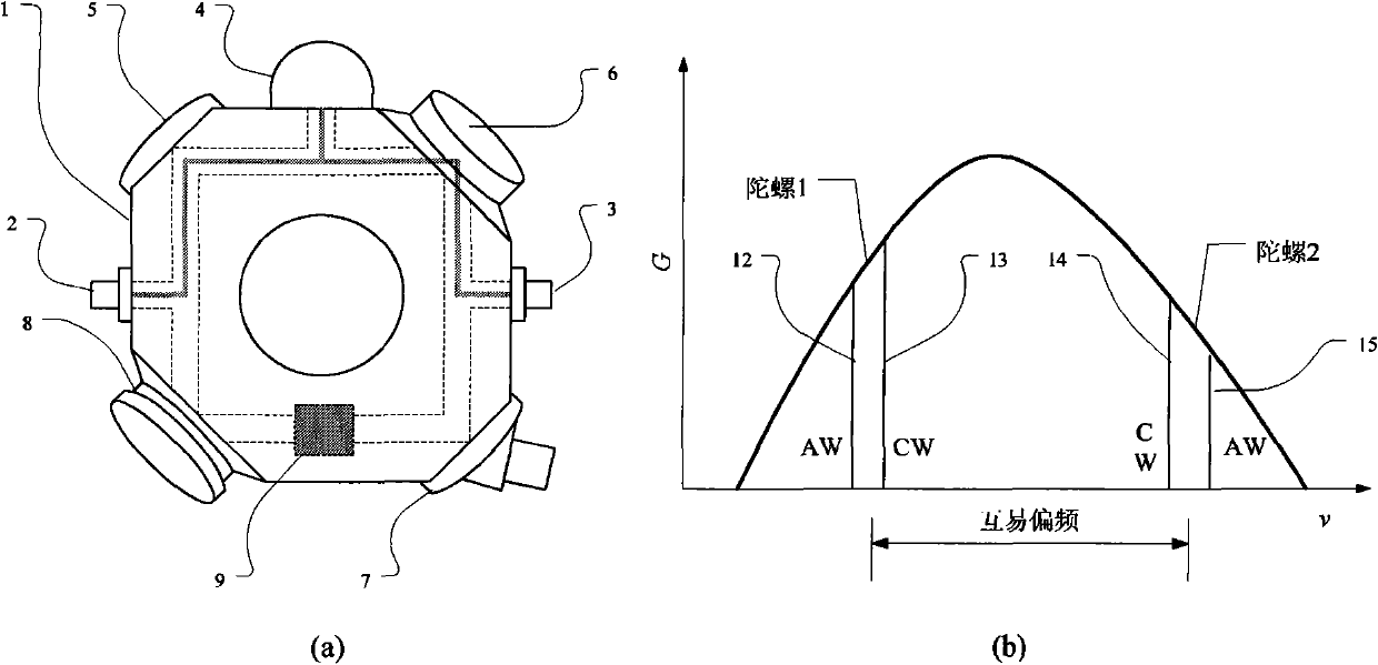
[0029] figure 1 is the schematic diagram of the four-frequency laser gyro structure and its mode distribution on the gain curve. Air-filled and light-transmitting ducts are processed on the low-expansion glass-ceramic cavity 1, and four reflectors 5, 6, 7, and 8 are installed on the four corners of the cavity, of which 7 is an output mirror with a slightly larger transmittance . Applying a high voltage across the anodes 2, 3 and cathode 4 creates a DC discharge to provide gain. 10 is a reciprocal frequency bias element, which provides bias frequency for two single gyros of the four-frequency laser gyro to avoid mode competition. 9 is a non-reciprocal frequency bias element, which provides non-reciprocal frequency bias for two modes of the same polarization in the four-frequency laser gyroscope to avoid locking. The positions of the four modes of the four-fr...


PUM


Abstract

The invention discloses a four-frequency laser gyro signal reading method based on electronic signal processing. In the method, the separation of beat-frequency signals of two single gyros is finished by electronic signal processing instead of optical signal processing, so that beams output by a four-frequency differential laser gyro can be mixed together by means of only one simple prism, and the sensitive angular velocity of the four-frequency laser gyro can be extracted from the mixed beams by using the electronic signal processing algorithm. The simplified beam-combining assembly has the advantages of less attenuation of optical signals, simple structure and higher firmness and is easy to assemble.

Description

technical field [0001] The invention relates to a signal readout method of a four-frequency laser gyroscope, which includes a light-combining component, a photodetector and an electronic signal processing circuit, and is suitable for a laser gyroscope with four traveling wave modes running in a cavity. Background technique [0002] Laser gyro has the advantages of large dynamic range, no acceleration effect, and simple structure. It is an ideal component for inertial systems, especially strapdown inertial systems, and has been widely used in military and civilian fields. The principle of the laser gyroscope is the Sagnac effect, and at least one pair of counterpropagating light waves run in its optical resonant cavity. When it rotates around the sensitive axis relative to the inertial space, the frequency of the opposite traveling waves splits to form a beat frequency proportional to the rotation rate, so the rotation information of the laser gyroscope relative to the inerti...

Claims


Application Information

Patent Timeline
Patent Type & Authority Applications(China)
IPC IPC(8): G01C19/66
Inventor 龙兴武汪之国王飞
Owner NAT UNIV OF DEFENSE TECH
Why Eureka
Try Eureka