Peak-valley motion detection method and device for measuring sub-pixel displacement

A detection method and sub-pixel technology, applied in the direction of measuring devices, optical devices, instruments, etc., can solve the problems of fluctuations, blurring, and large changes in light intensity data of grayscale images

Inactive Publication Date: 2013-04-03
CHONGQING TECH & BUSINESS UNIV
View PDF9 Cites 0 Cited by
  • Summary
  • Abstract
  • Description
  • Claims
  • Application Information

AI Technical Summary

Problems solved by technology

For example, due to the short frequency of visible light, the reflected light of an object that is photoelectrically converted by a photoelectric sensor will be an average value of several reflections; with the different illumination angles, the diffuse reflection of a rough surface will be very strong, and the change will also vary. will be larger; the reflected light produced by strong reflective surfaces such as metals and flat mirrors will change strongly with the change of the incident light angle, and even the images of other surrounding objects will be reflected, which will be blurred , confuse the texture characteristics of the reflective surface itself; the incident sunlight will be rich in polarized light after being reflected by the object; the influence of radiation from other light sources in the measurement environment or floating dust or smoke will also cause image frames on the surface of the measured object Overall or local light intensity changes, or random fluctuations in the light intensity data of the grayscale image

Method used


Image

  • Peak-valley motion detection method and device for measuring sub-pixel displacement
  • Peak-valley motion detection method and device for measuring sub-pixel displacement
  • Peak-valley motion detection method and device for measuring sub-pixel displacement

Examples


Embodiment Construction

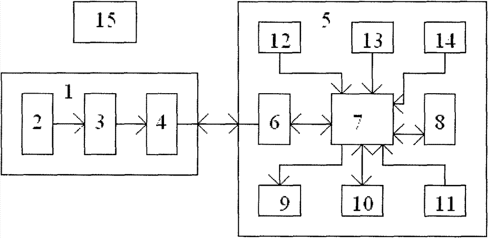
[0099] figure 1 is a block diagram of the measuring device of the present invention. Described camera head (1) is made up of optical lens (2), photoelectric imaging chip (3) and the USB interface (4) of camera head, is connected to the USB interface (5) of a common computer system (5) by its configured USB cable 6), the computer system (5) is also equipped with CPU (7), internal memory (8), display card and monitor (9), hard disk (10), keyboard and mouse (11), operating system (12), camera driver Program (13) and sub-pixel displacement program (14) for camera capture and peak / valley motion detection.

[0100] First, run the camera driver (13) distributed with the camera (1) on the computer (5), and install the camera (1) to the computer (5). The focal length of the optical lens (2) of the camera (1) is adjusted so that the image of the measured object is clear.

[0101] Then, the measurement environment is selected, or the related lighting equipment (15) is adjusted, so tha...


PUM


Abstract

The invention relates to a peak-valley motion detection method and a peak-valley motion detection device for measuring sub-pixel displacement. The peak-valley motion detection device for measuring the sub-pixel displacement consists of a common computer and a camera thereof. The peak-valley motion detection method for measuring the sub-pixel displacement comprises the following steps of: shootingone frame and selecting an observation line and an observation row with the most reflection characteristics of a measured object according to side direction data along a coordinate direction; then shooting one frame and determining the respective side direction data, the peak and the valley of three primary colors of the two frames; if the number of the peak or the valley of the mutual displacement relationship between the observation line and the observation row and certain preset percentage exceeding the number of the peak and the valley of each axial primary color are not determined through comparison, determining 'mistrack' and shooting one frame again; and if the number of the peak or the valley of the mutual displacement relationship between the observation line and the observation row and certain preset percentage exceeding the number of the peak and the valley of the axial primary color are determined through comparison, calculating the sub-pixel displacement of each primary color in each axial direction respectively according to the moving directions and the number of the peak and the valley of each primary color in the successively continuous two frames and taking the average value as the total displacement. The influence of ambient illumination change is effectively overcome, and the device and the method are suitable for the occasion where the speeds of the displacement and the illumination change are far lower than the speed of the shooting frames.

Description

technical field [0001] The invention belongs to the technical field of digital image measurement, in particular to a method and a device for non-contact two-dimensional micro-displacement measurement of an object by using a computer camera. Background technique [0002] Computer cameras have gained popularity rapidly in recent years, and are generally used for network video chatting or surveillance shooting. The core is CCD and CMOS photoelectric imaging chips, that is, photoelectric sensor arrays. The core of the optical orientation device invented before it is also a photodetection pixel array, which is used to detect its two-dimensional movement relative to the surface on which it is located. Therefore, it is beneficial to investigate optical orientation devices for wide-open camera applications. [0003] U.S. Pat. No. 5,288,993 discloses a cursor orienting device utilizing an array of photodetectors in which an illuminated target sphere must have randomly distributed ma...

Claims


Application Information

Patent Timeline
Patent Type & Authority Patents(China)
IPC IPC(8): G01B11/02
Inventor 曾艺
Owner CHONGQING TECH & BUSINESS UNIV
Why Eureka
Try Eureka