
Heat pipe and heat pipe based guide type aluminium electrolysis cell

An aluminum electrolytic cell and heat pipe technology, which is used in indirect heat exchangers, lighting and heating equipment, etc., can solve the problem that cold tanks or aluminum electrolytic cells are weak against thermal disturbances, deteriorate the production environment of aluminum electrolysis workshops, and reduce the life of diversion electrolytic cells. Low problems, to achieve uniform temperature distribution in the tank, improve heat utilization, and simple structure

Inactive Publication Date: 2011-04-20
CHANGSHA UNIVERSITY OF SCIENCE AND TECHNOLOGY
View PDF8 Cites 3 Cited by
  • Summary
  • Abstract
  • Description
  • Claims
  • Application Information

AI Technical Summary

Problems solved by technology

However, there are still the following problems in this diversion type aluminum electrolytic cell: 1. Due to the reduction of the pole distance, the heat generated by the aluminum electrolytic cell will inevitably decrease, resulting in weak resistance to thermal disturbance of the cold tank or aluminum electrolytic cell, which will affect the performance of aluminum electrolysis Normal production; 2. The diversion-type aluminum electrolytic cell cannot change the defects of large heat dissipation loss of the electrolytic cell and seriously deteriorates the production environment of the aluminum electrolysis workshop; 3. Because the side temperature of the diversion-type aluminum electrolytic cell is much higher than The temperature at the bottom of the tank results in relatively large thermal stress in the tank, and for diversion-type aluminum electrolytic cells with poly-aluminum grooves on the cathode, it is more sensitive to thermal stress, which will inevitably lead to a relatively low service life of the diversion-type electrolytic cell

Method used


Image

  • Heat pipe and heat pipe based guide type aluminium electrolysis cell
  • Heat pipe and heat pipe based guide type aluminium electrolysis cell
  • Heat pipe and heat pipe based guide type aluminium electrolysis cell

Examples


Embodiment Construction

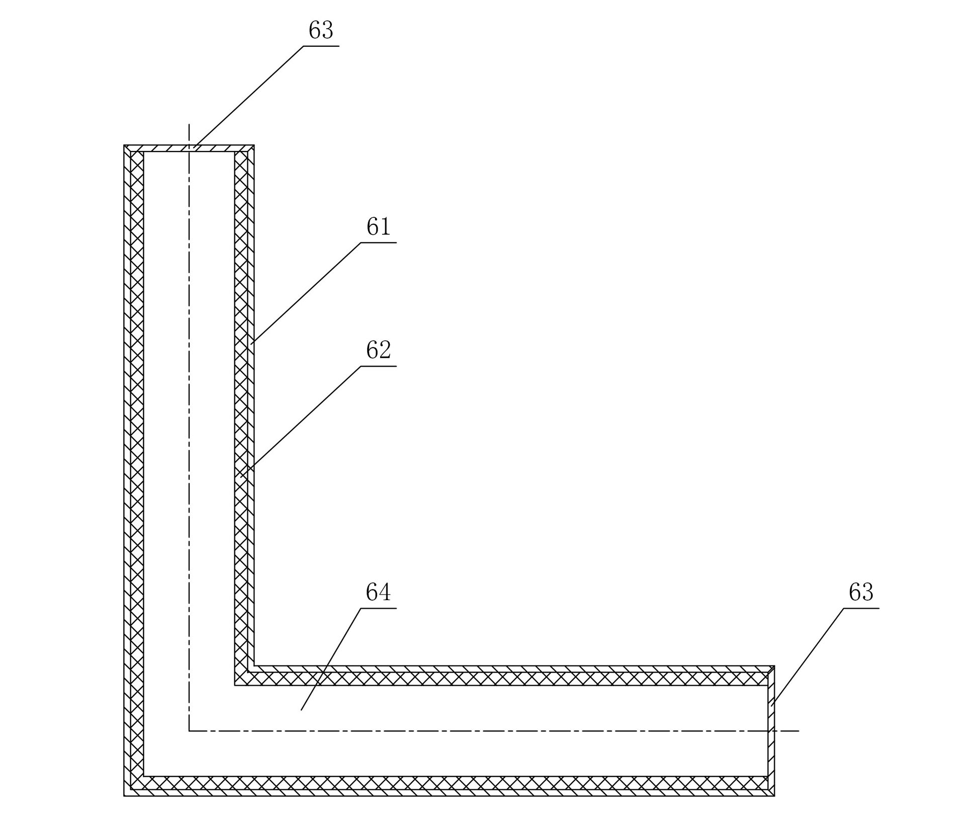
[0019] figure 1 A heat pipe embodiment of the present invention is shown, the heat pipe includes a tube shell 61, a liquid-absorbing core 62 and a sealing end cap 63, the tube shell 61 is L-shaped, and the liquid-absorbing core 62 is covered on the inner wall of the tube shell 61, The sealing end caps 63 are mounted on both ends of the tube shell 61 to form a closed lumen 64, and the sealed lumen 64 is filled with working fluid. The heat pipe of the present invention is simple in structure, easy to manufacture, and low in cost. The L-shaped shell 61 is convenient to be installed in the aluminum electrolytic cell, and transfers the heat from the side of the aluminum electrolytic cell to the bottom; The working liquid is absorbed by the liquid-absorbing core 62 and sent to the evaporating section, where the working liquid absorbs heat and turns into a gas, and then returns to the condensation section through the sealed lumen 64 to release heat and turn back into a liquid. This c...


PUM


Abstract

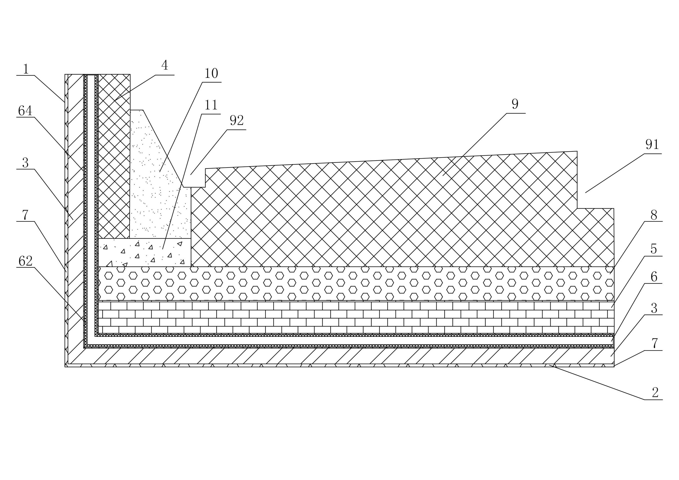
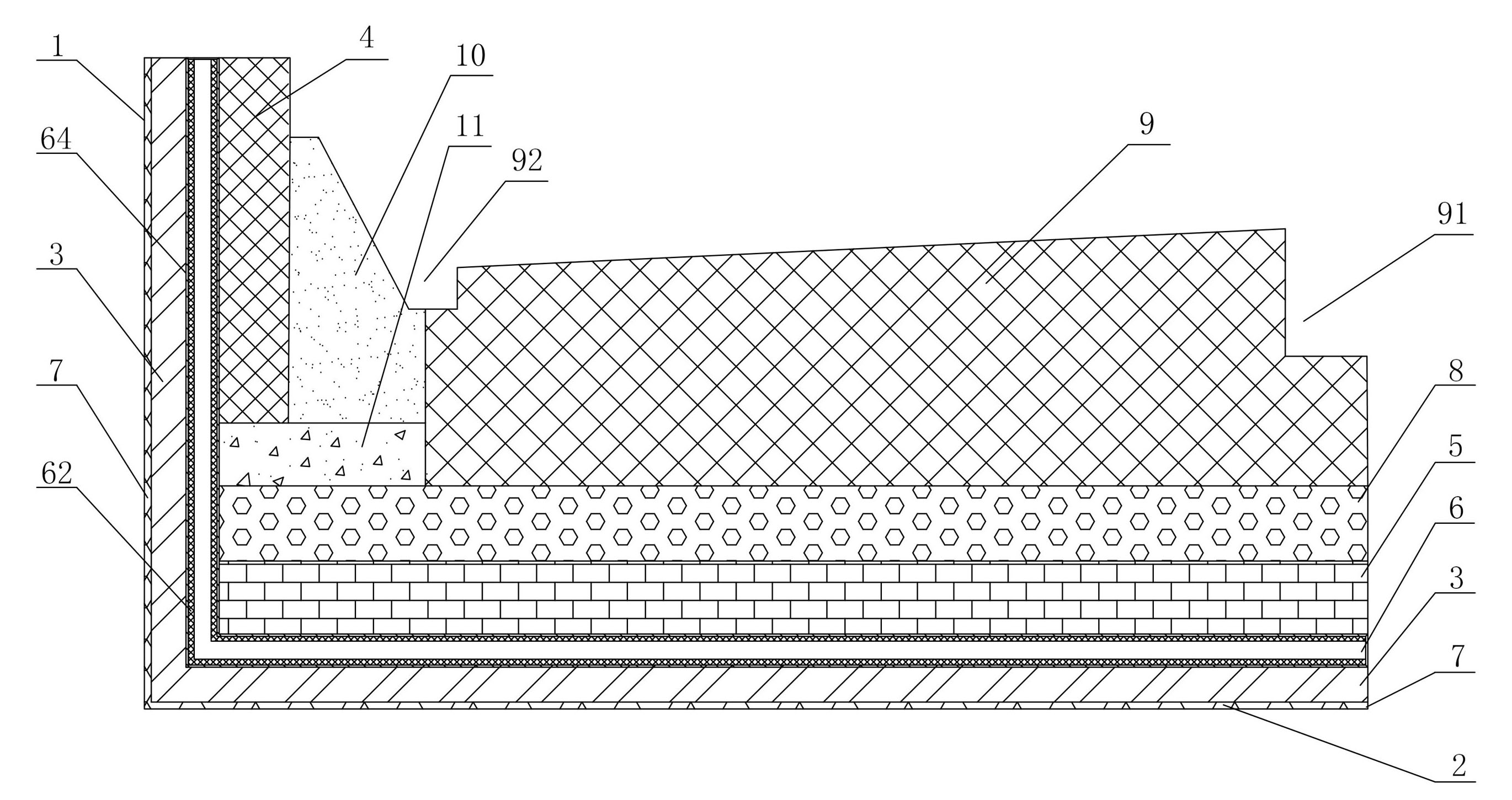
The invention discloses a heat pipe which comprises a pipe case, a wick and sealed end covers, wherein the pipe case is in an L shape, the wick is covered on the inner wall of the pipe case, the sealed end covers are arranged at the two ends of the pipe case so as to form a sealed pipe cavity, and the sealed pipe cavity is filled with working fluid. The heat pipe has the advantages that the structure is simple, and heat at the side wall of an aluminium electrolysis cell can be conveniently transferred to the bottom of the cell. The invention also discloses a heat pipe based guide type aluminium electrolysis cell which comprises a cell body, wherein the outer side of the cell body is provided with a heat insulation brick layer, the cell body is provided with a side carbon block at the inner side of the side wall, the cell body is provided with a fireproof brick layer at the inner side of the bottom of the cell, a cathode carbon block is arranged above the fireproof brick layer, the middle of the cathode carbon block is provided with a central aluminium accumulation sump, the two sides of the cathode carbon block are connected with the side carbon block by the tamping paste, the joint of the tamping paste and the cathode carbon block is provided with a peripheral aluminium accumulation sump, and the cell body is internally provided with the heat pipe. The aluminium electrolysis cell has the advantages that the radiation loss of the side of the aluminium electrolysis cell can be reduced, the heat utilization ratio of the aluminium electrolysis cell can be improved, and the service life is long.

Description

technical field [0001] The invention relates to the field of nonferrous metallurgy, in particular to a heat pipe for transferring heat in nonferrous metallurgy equipment and a flow-guiding aluminum electrolytic cell based on the heat pipe. Background technique [0002] Since the Hall-Elut electrolytic aluminum smelting method was born in 1888, it has been the only method for large-scale aluminum smelting in industry. For more than 100 years, people have made unremitting efforts to improve the current efficiency and reduce energy consumption of aluminum electrolytic cells, so that the current efficiency has been increased from about 60% to the current best level of 96%, and the DC power consumption has been reduced from 41900kWh / t-Al has dropped to 12900kWh / t-Al, and the service life of aluminum electrolytic cells has reached more than 5 years. Under the conditions of existing technical equipment, if the aluminum electrolysis process and equipment do not change fundamentally...

Claims


Application Information

Patent Timeline
Patent Type & Authority Applications(China)
IPC IPC(8): F28D15/02C25C3/08
Inventor 姜昌伟
Owner CHANGSHA UNIVERSITY OF SCIENCE AND TECHNOLOGY
Learn More