Disc type magnetic control speed governing clutch
A clutch and speed regulation technology, applied in the field of clutches, can solve the problems of high manufacturing, use and maintenance costs, high manufacturing costs, and short life, and achieve low maintenance and use costs, low product costs, and long service life.
- Summary
- Abstract
- Description
- Claims
- Application Information
AI Technical Summary
Problems solved by technology
Method used
Image
Examples
Embodiment 1
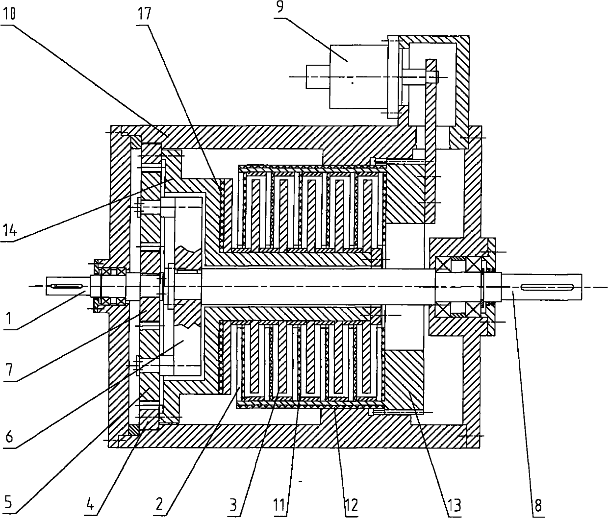
[0053] see figure 1 According to the first embodiment of the present invention, the disk-type magnetically controlled speed regulating clutch includes an input shaft 1, a brake disk 2, a linkage disk 3, a speed regulating wheel 4, a planetary gear 5, a planetary carrier 6, a sun gear 7, Output shaft 8 , adjustment mechanism 9 , body 10 , spacer disk 11 , magnetic spacer sleeve 12 , braking body 13 , linkage body 14 and insulator 17 .
[0054] The input shaft 1 and the output shaft 8 are installed on the body 10, the sun gear 7 is connected with the input shaft 1, and can rotate together with the input shaft 1, the planetary gear 5 is installed on the planet carrier 6, and the planet carrier 6 and the output shaft 8 They are connected together and can rotate together with the output shaft 8. The planetary gear 5 meshes with the sun gear 7 inwardly and meshes with the flywheel 4 outwardly. The planetary gear 5 can rotate around its own axis and can revolve around the sun. The w...
Embodiment 2
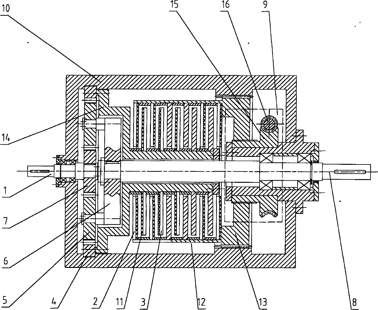
[0060] see figure 2 According to the second embodiment of the present invention, the disk-type magnetically controlled speed regulating clutch includes an input shaft 1, a brake disk 2, a linkage disk 3, a speed regulating wheel 4, a planetary gear 5, a planetary carrier 6, a sun gear 7, Output shaft 8, adjustment mechanism 9 (part shown in dotted line), machine body 10, spacer disk 11, brake body 13, linkage body 14, worm wheel 15 and worm screw 16.
[0061] The input shaft 1, the output shaft 8 and the flywheel 4 are installed on the body 10, the sun gear 7 is connected with the input shaft 1 and can rotate together with the input shaft 1, the planetary gear 5 is installed on the planetary carrier 6, and the planetary carrier 6 is connected with the output shaft 8 and can rotate together with the output shaft 8. The planetary gear 5 meshes with the sun gear 7 and the flywheel 4 at the same time. The sun gear 7, the planetary gear 5 and the flywheel 4 can all rotate around t...
Embodiment 3
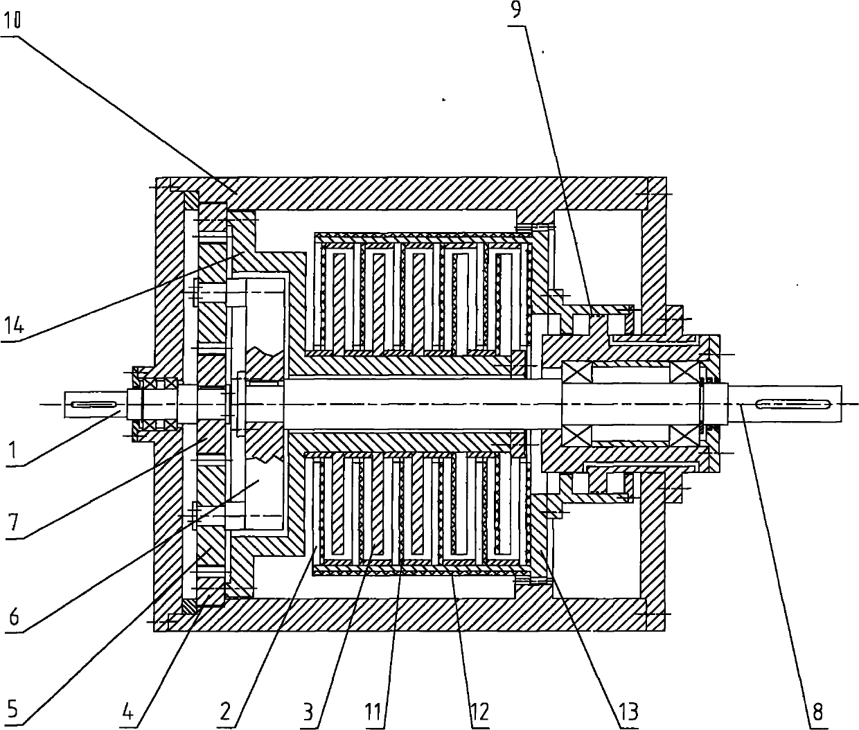
[0064] see image 3 According to the third embodiment of the present invention, the disk-type magnetically controlled speed regulating clutch includes an input shaft 1, a brake disk 2, a linkage disk 3, a speed regulating wheel 4, a planetary gear 5, a planetary carrier 6, a sun gear 7, Output shaft 8, adjustment mechanism 9, machine body 10, spacer disk 11, magnetic spacer sleeve 12, brake body 13, linkage body 14.
[0065]The input shaft 1, the output shaft 8 and the flywheel 4 are installed on the body 10, the input shaft 1 is connected with the sun gear 7, and can rotate together with the sun gear 7, the planetary gear 5 is installed on the planetary carrier 6, and the planetary carrier 6 is connected with the output shaft 8 and can rotate together with the output shaft 8. The planetary gear 5 is located between the sun gear 7 and the flywheel 4 and meshes with the sun gear 7 and the flywheel 4 at the same time. The sun gear 7, Both the planetary gear 5 and the flywheel 4...
PUM
 Abstract
Description
Claims
Application Information
 - R&D Engineer
- R&D Manager
- IP Professional
- Industry Leading Data Capabilities
- Powerful AI technology
- Patent DNA Extraction
Browse by: Latest US Patents, China's latest patents, Technical Efficacy Thesaurus, Application Domain, Technology Topic, Popular Technical Reports.
© 2024 PatSnap. All rights reserved.Legal|Privacy policy|Modern Slavery Act Transparency Statement|Sitemap|About US| Contact US: help@patsnap.com


