Joint

一种连接杆、枢接部的技术,应用在可摆动的接头领域,能够解决连接装置难满足等问题

Inactive Publication Date: 2014-01-15
HONG FU JIN PRECISION IND (SHENZHEN) CO LTD +1
View PDF3 Cites 0 Cited by
  • Summary
  • Abstract
  • Description
  • Claims
  • Application Information

AI Technical Summary

Problems solved by technology

However, when the surface morphology of the workpiece to be polished is relatively complex, it is often necessary for the driven element connected to the grinding equipment to have a swing and reset function relative to the active element. It is generally difficult for the existing connecting device to meet the above requirements

Method used


Image

  • Joint
  • Joint
  • Joint

Examples


Embodiment Construction

[0010] The joint of the present invention will be further described in detail with reference to the accompanying drawings and embodiments.

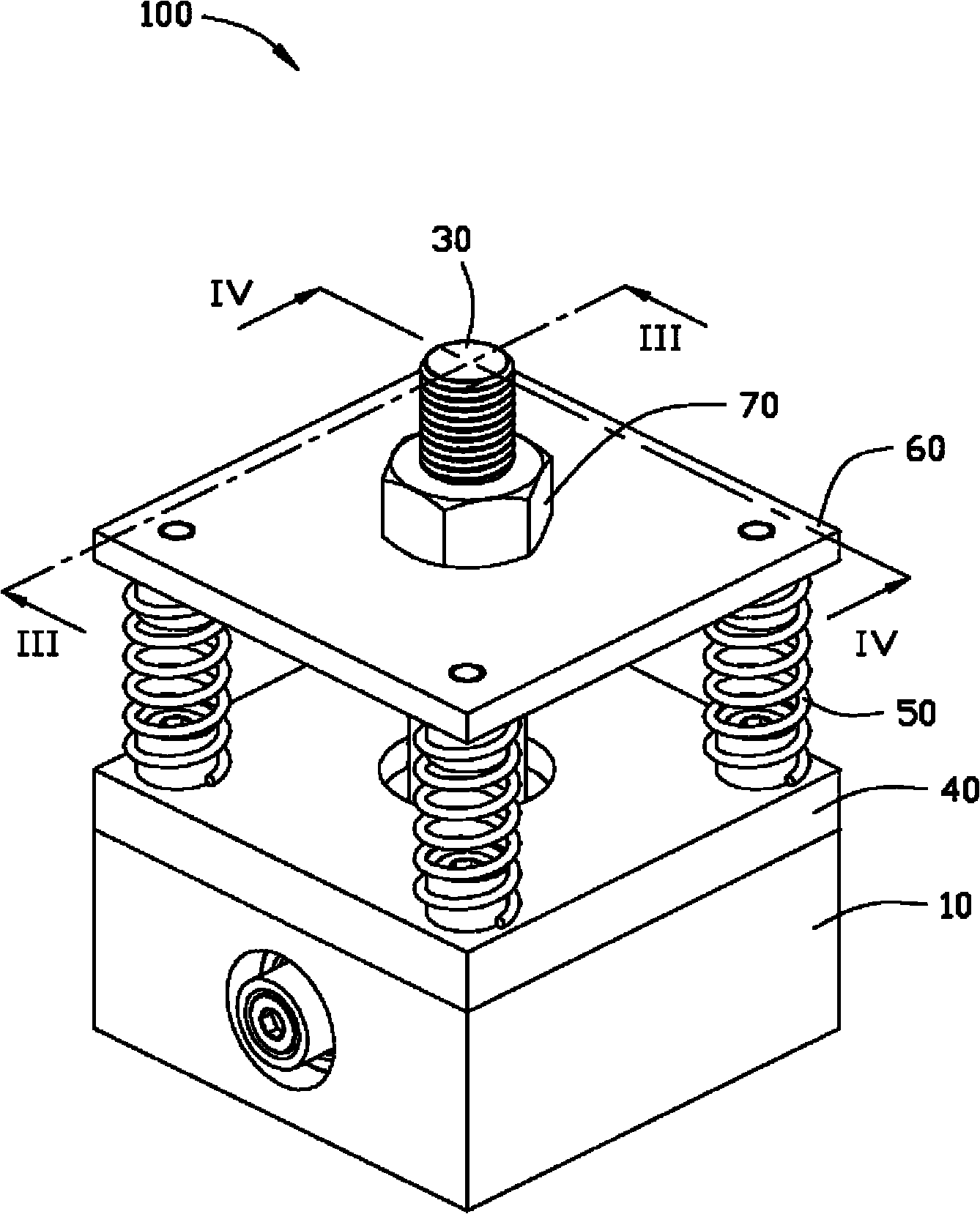
[0011] see figure 1 , the joint 100 of the embodiment of the present invention includes a fixing seat 10 , a connecting rod 30 , four elastic members 50 and a positioning plate 60 . The connecting rod 30 is movably connected with the fixed base 10 and can flexibly swing around relative to the fixed base 10 . The positioning plate 60 is sleeved on the connecting rod 30 , and the four elastic members 50 are disposed between the positioning plate 60 and the fixing seat 10 .

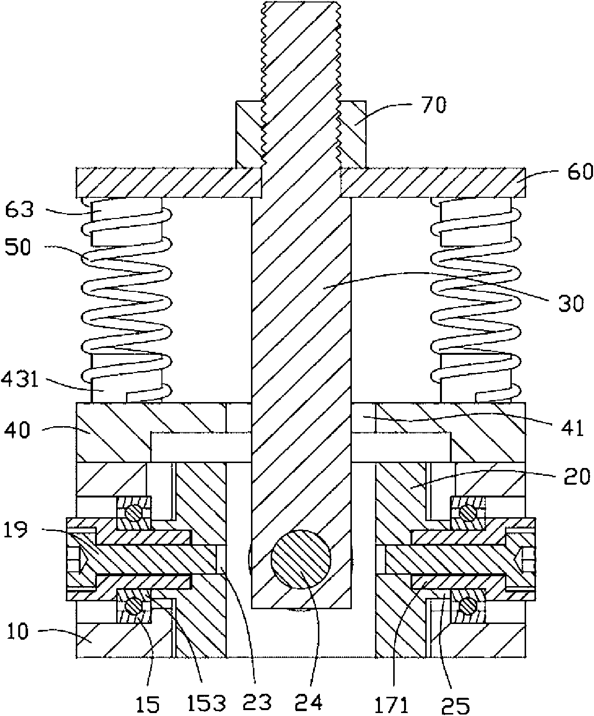
[0012] Please also see figure 2 , the fixing seat 10 is roughly a square block, and a square receiving cavity 11 is opened in the middle thereof. Two opposite side walls of the fixing base 10 along the X-axis as shown in the figure are respectively provided with an axis hole 13 communicating with the accommodating cavity 11 .

[0013] The joint 100 also includes tw...


PUM


Abstract

A joint includes a first retaining base, a connecting rod, a positioning plate, and at least two elastic members. The connecting rod is movably connected to the first retaining base. The positioning plate is fixed to the connecting rod. The at least two elastic members are disposed between the first retaining base and the positioning plate. The at least two elastic members are arranged along a circumference of the connecting rod.

Description

technical field [0001] The invention relates to a joint, in particular to a swingable joint. Background technique [0002] With the development of industry, automation equipment has been widely used in various production fields, such as manipulators capable of grasping and moving, which can move according to the set trajectory, and cooperate with the grinding device to achieve grinding and polishing of the workpiece. The connection between the active element and the driven element of the existing manipulator mostly adopts a rigid fixed connection. However, when the surface morphology of the workpiece to be polished is relatively complex, it is often necessary for the driven element connected to the grinding equipment to have a swing and reset function relative to the active element. It is generally difficult for existing connecting devices to meet the above requirements. Contents of the invention [0003] In view of the above situation, it is necessary to provide a joint ...

Claims


Application Information

Patent Timeline
Patent Type & Authority Patents(China)
IPC IPC(8): B25J19/00
CPCB25J17/0208B25J17/0275Y10T403/75Y10T403/45
Inventor 宋尚轩张成
Owner HONG FU JIN PRECISION IND (SHENZHEN) CO LTD
Why Eureka
Try Eureka