Wireless communication system, transmitter apparatus, receiver apparatus, and communication method
A technology of wireless communication system and transmission equipment, applied in the direction of wireless communication, transmission system, baseband system, etc., can solve the problem that the intersection point is not improved and so on
- Summary
- Abstract
- Description
- Claims
- Application Information
AI Technical Summary
Problems solved by technology
Method used
Image
Examples
no. 1 example
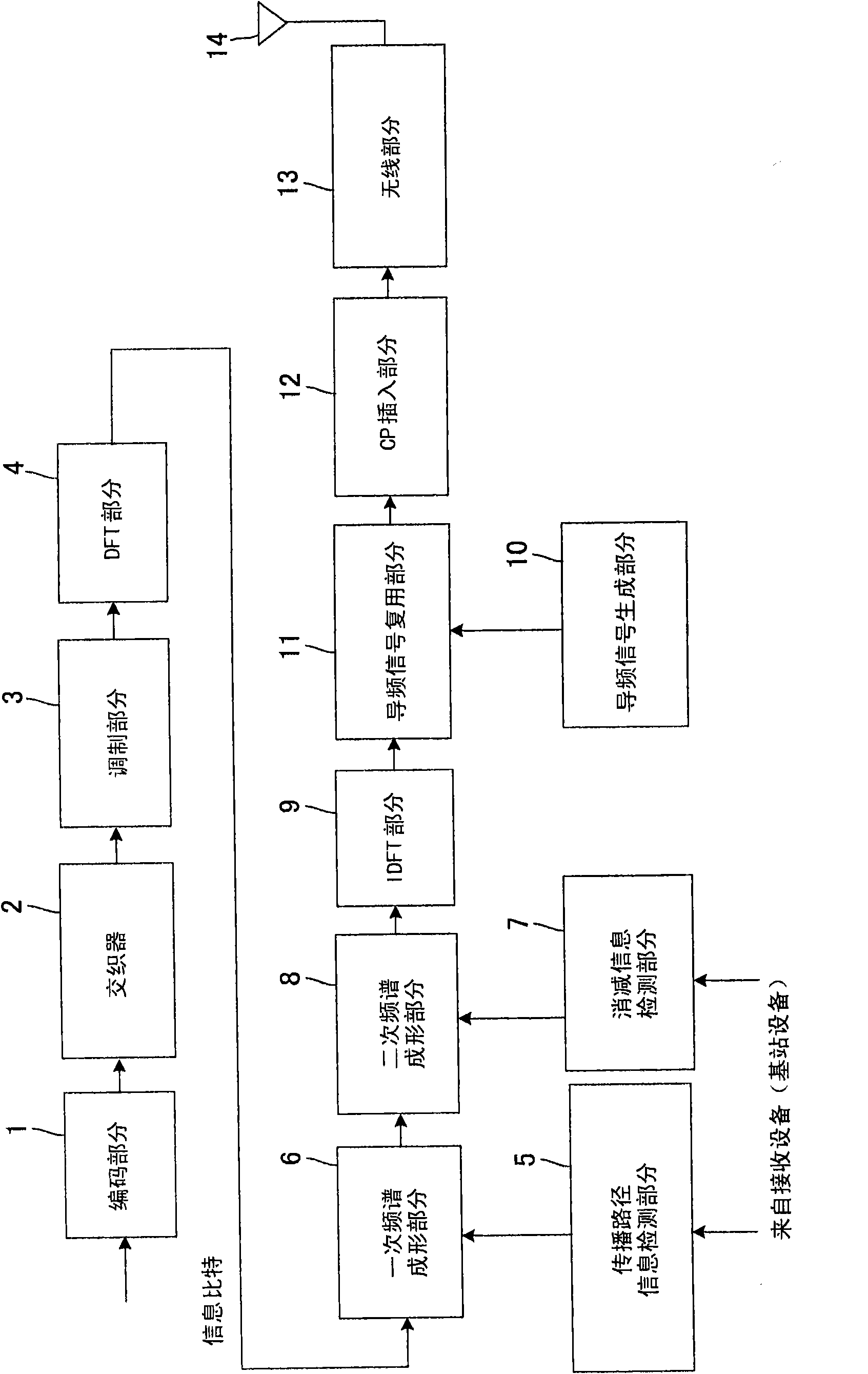
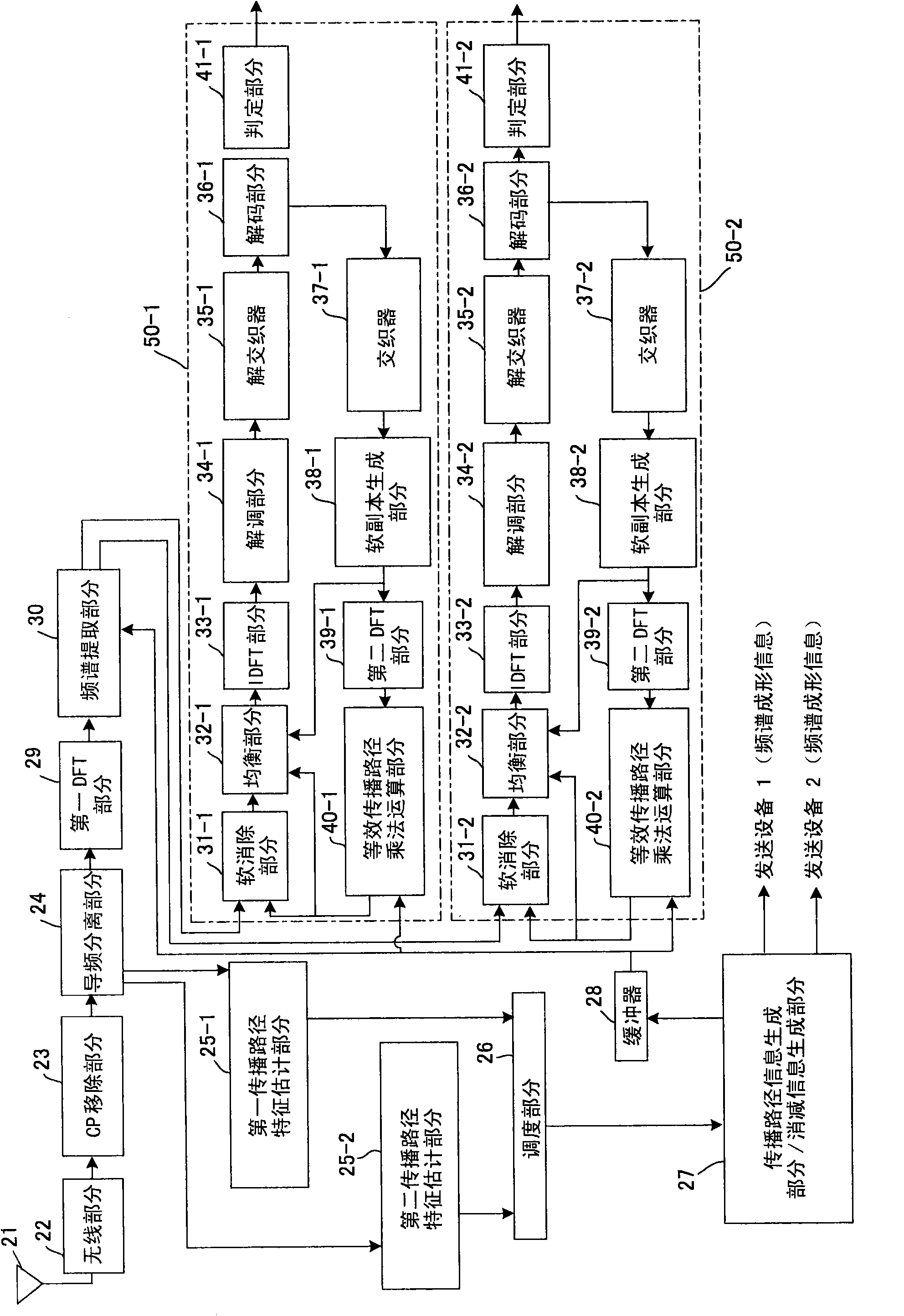
[0073] As a first embodiment, a description will be made for the case of adaptively controlling the ratio at which the frequency spectrum is clipped when overlapping is not allowed. An example of a sending device (mobile station device) is figure 1 shown. The sending device includes a coding unit 1, an interleaver 2, a modulation unit 3, a DFT unit 4, a propagation path information detection unit 5, a primary spectrum shaping unit 6, a subtraction information detection unit 7, a secondary spectrum shaping unit 8, an IDFT (discrete Fourier transform Inverse transform) unit 9 , pilot signal generation unit 10 , pilot signal multiplexing unit 11 , CP insertion unit 12 , wireless unit 13 , and transmission antenna 14 .
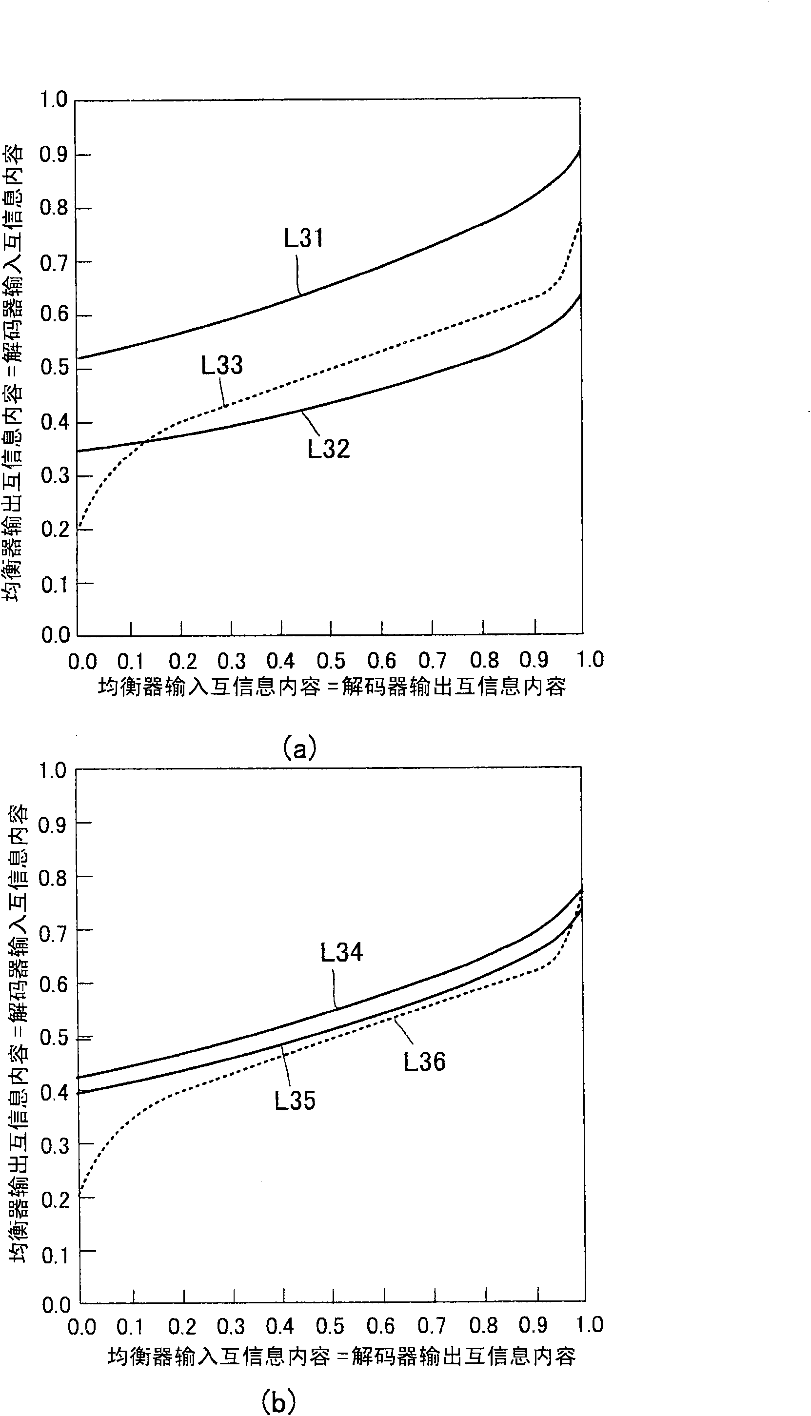
[0074] First, error correction coding is performed on the information bits in the coding unit 1, and the obtained coded bits are rearranged in the interleaver 2. The interleaved coded bits are modulated in the modulation unit 3 and converted into frequency sign...
no. 2 example
[0125] In the first embodiment, the description has been made on the case where signals from all transmission devices are made to be orthogonal on the frequency axis without overlapping. However, since the reception device (base station device) has an interference prevention function, even when overlap occurs, even signals from other transmission devices can be input to the canceller for the overlapped spectrum, and each transmission device is detected in the canceller. The intersymbol interference component in the signal, and when eliminated together, the signal can be completely separated.
[0126] Figure 6 The concept of primary spectrum shaping and secondary spectrum shaping when overlapping of signals of each transmitting device is shown. Figure 6 (a) shows the concept of primary spectrum shaping (overlapping spectrum B1), and the control is based on the same water filling principle as that of the first embodiment, so its description is omitted. Figure 6 (b) shows th...
no. 3 example
[0134] As a third embodiment, the embodiments so far have shown the case where the encoding rates of all transmitting devices are the same, however, in this embodiment, the encoding rate of the error correction coding applied by each transmitting device can also be controlled together. When the error correction coding is convolutional coding, the coding rate is 1 / 8, 1 / 7, 1 / 6, 1 / 5, 1 / 4, 1 / 3, 1 / 2, 2 / 3, 3 / 4, 4 / In the case of 5, 5 / 6, 6 / 7 and 7 / 8, the input and output characteristics of the mutual information of the decoder are as follows Figure 12 shown. In the figure, 201 denotes a decoder characteristic of a coding rate of 1 / 8, and similarly, 202 to 212 respectively denote decoder characteristics of a coding rate in the order described above. Additionally, with Figure 11 In the same way, the vertical axis shows the decoder input mutual information, and the horizontal axis shows the decoder output mutual information. Since both input and output characteristics are uniquely d...
PUM
 Abstract
Description
Claims
Application Information
 - R&D
- Intellectual Property
- Life Sciences
- Materials
- Tech Scout
- Unparalleled Data Quality
- Higher Quality Content
- 60% Fewer Hallucinations
Browse by: Latest US Patents, China's latest patents, Technical Efficacy Thesaurus, Application Domain, Technology Topic, Popular Technical Reports.
© 2025 PatSnap. All rights reserved.Legal|Privacy policy|Modern Slavery Act Transparency Statement|Sitemap|About US| Contact US: help@patsnap.com


