Scroll compressor
A scroll compressor and scroll technology, applied in the field of scroll compressors, can solve problems such as leakage and performance deterioration
- Summary
- Abstract
- Description
- Claims
- Application Information
AI Technical Summary
Problems solved by technology
Method used
Image

Examples
Embodiment 1
[0212] Embodiments of the present invention will be described below with reference to the drawings. In addition, this invention is not limited to these Examples.
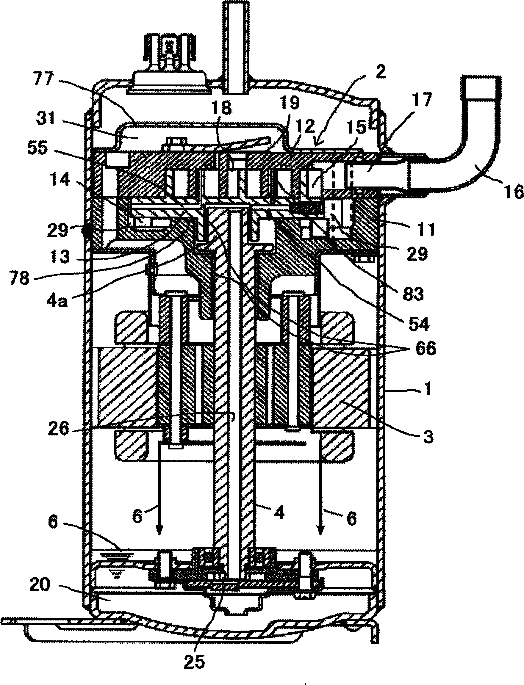
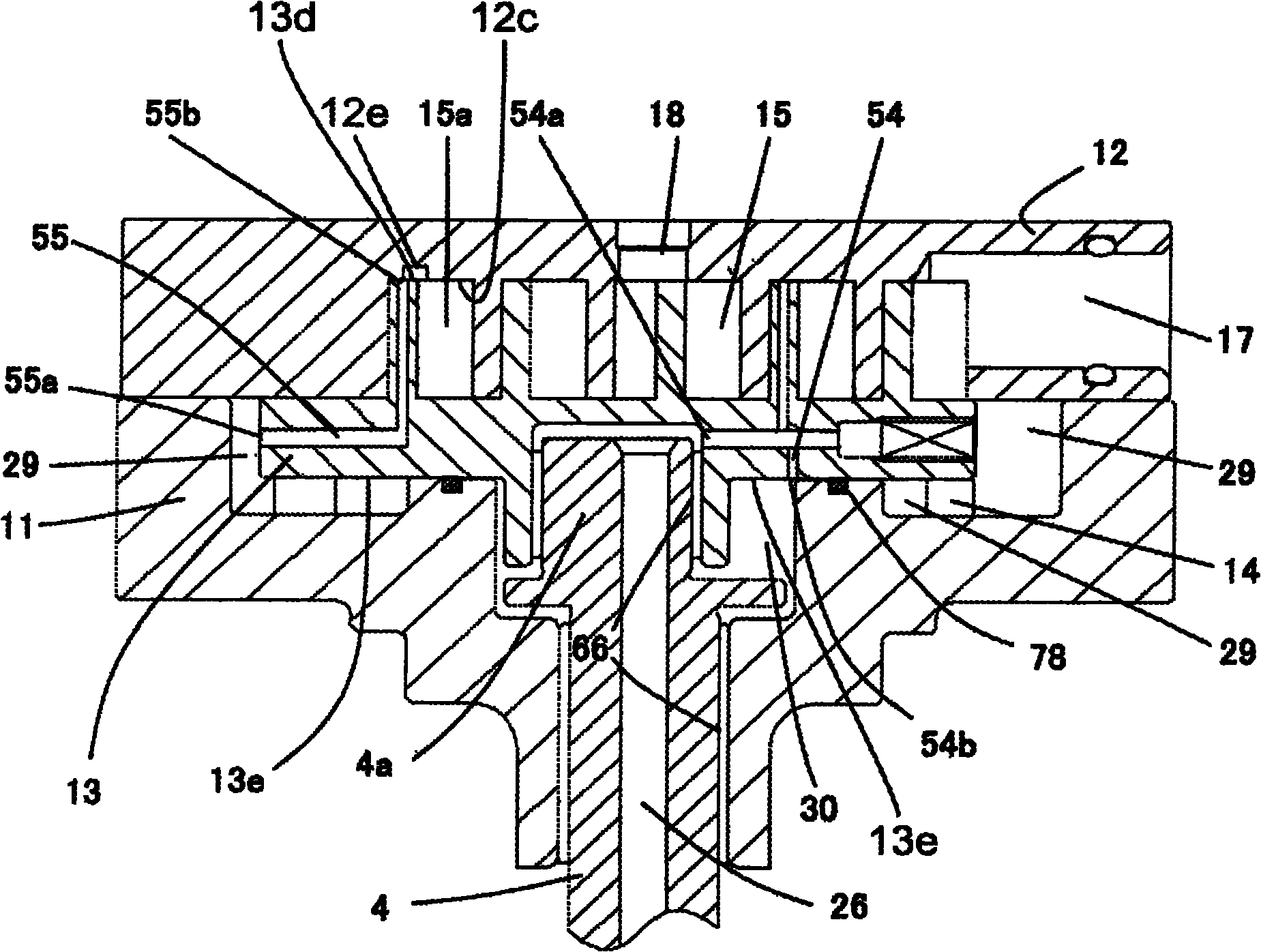
[0213] A first embodiment of the present invention will be described. figure 1 is a longitudinal sectional view of the scroll compressor in the first embodiment of the present invention, figure 2 yes figure 1 Cross-sectional view of the compression mechanism of a scroll compressor. Next, the structure, operation and function of the scroll compressor of the first embodiment will be described.
[0214] Such as figure 1 , figure 2 As shown, the scroll compressor of the present embodiment is constituted by an airtight container 1 , a compression mechanism 2 provided inside the airtight container 1 , a motor unit 3 , and an oil accumulator 20 .
[0215] Between the main bearing part 11 of the crankshaft 4 fixed by welding and heat press fitting in the airtight container 1 and the fixed scroll 12 fixed on the m...
Embodiment 2
[0253] A second embodiment of the present invention will be described. Figure 7 It is a sectional view of the compression mechanism of the scroll compressor in the second embodiment of the present invention. In this embodiment, parts of the invention that are different from those in Embodiment 1 will be described. That is, in Figure 7 in, for with figure 2 The same symbols are used for the same components, and descriptions thereof are omitted.
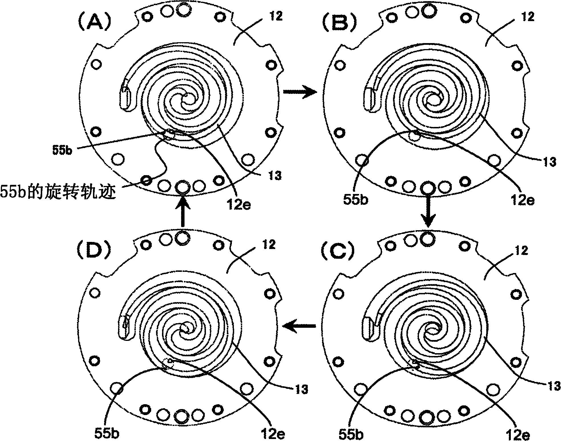
[0254] Such as Figure 7 As shown, in the scroll compressor of this embodiment, the second path 56 is composed of a second control path that passes from the back pressure chamber 29 through the interior of the orbiting scroll 13 and then communicates with the thrust surface 13f of the orbiting scroll 13 . Furthermore, the second control path is intermittently opened in the wrap groove 12g of the fixed scroll 12 according to the rotational motion.
[0255] Figure 8 is a cross-sectional view of a state where the orbiting scroll...
Embodiment 3
[0265] A third embodiment of the present invention will be described. Figure 9 is a longitudinal sectional view of a scroll compression mechanism in a third embodiment of the present invention, Figure 10 yes Figure 9 The cross-sectional view of the compression mechanism of the scroll compressor, Figure 11 yes Figure 10 The cross-sectional view of the fixed scroll and the orbiting scroll of the compression mechanism meshed with each other.
[0266] Such as Figure 9 As shown, in the scroll compressor of this embodiment, the main bearing part 11 of the crankshaft 4 fixed by means of welding and shrink fit in the airtight container 1 and the fixed scroll 12 fixed on the main bearing part 11 with bolts Between them, the orbiting scroll 13 meshing with the fixed scroll 12 is interposed, constituting the scroll compression mechanism 2 . Further, between the orbiting scroll 13 and the main bearing member 11, a rotation restricting mechanism 14 is provided, and the rotation ...
PUM
 Abstract
Description
Claims
Application Information
 - R&D
- Intellectual Property
- Life Sciences
- Materials
- Tech Scout
- Unparalleled Data Quality
- Higher Quality Content
- 60% Fewer Hallucinations
Browse by: Latest US Patents, China's latest patents, Technical Efficacy Thesaurus, Application Domain, Technology Topic, Popular Technical Reports.
© 2025 PatSnap. All rights reserved.Legal|Privacy policy|Modern Slavery Act Transparency Statement|Sitemap|About US| Contact US: help@patsnap.com