
Printed circuit board with radio frequency identification and production method thereof

A printed circuit board, radio frequency identification technology, applied in the direction of printed circuit manufacturing, including printed electrical components, printed circuits, etc., can solve problems such as inability to effectively track logistics dynamics, low work accuracy, and incorrect product quantity. Achieve the effect of increasing visibility and consulting accuracy, reducing costs and handling costs, and improving work accuracy

Inactive Publication Date: 2011-04-13
上海中京电子标签集成技术有限公司 +5
View PDF0 Cites 9 Cited by
  • Summary
  • Abstract
  • Description
  • Claims
  • Application Information

AI Technical Summary

Problems solved by technology

[0005] 1. The electronic tag reader equipment in the radio frequency identification (RFID) system of this prior art cannot directly print the RFID chip and the RFID antenna on the printed circuit board, and the labor cost is high.
[0006] 2. The electronic tag reader equipment in the radio frequency identification (RFID) system of this prior art has low working accuracy, complex manufacturing process, cannot ensure product quality, and slow processing speed
[0007] 3. The electronic tag reader equipment in the radio frequency identification (RFID) system of this prior art cannot effectively track the logistics dynamics, cannot effectively prevent the goods containing the RFID tag from being stolen, and the product quantity is incorrect, etc.

Method used


Image

  • Printed circuit board with radio frequency identification and production method thereof
  • Printed circuit board with radio frequency identification and production method thereof
  • Printed circuit board with radio frequency identification and production method thereof

Examples


Embodiment Construction

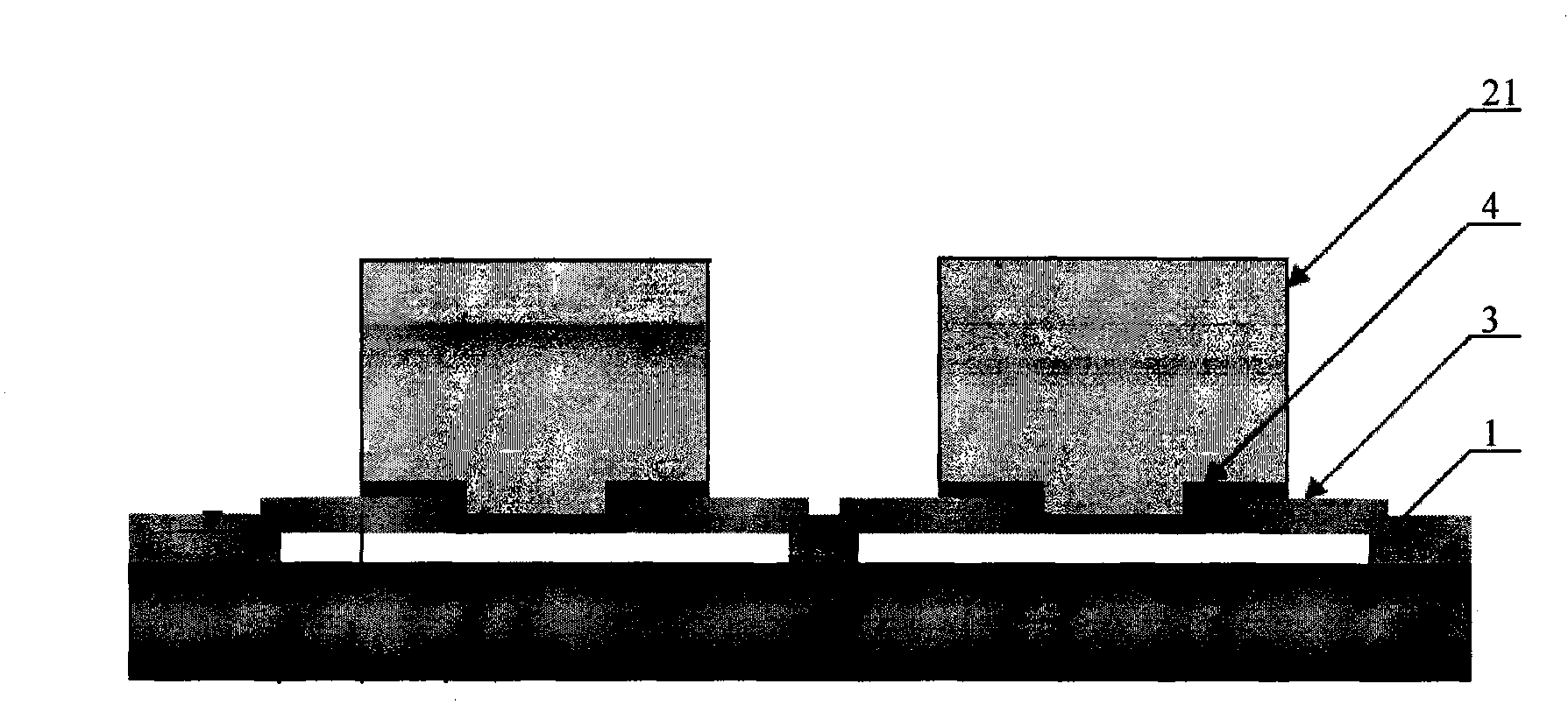
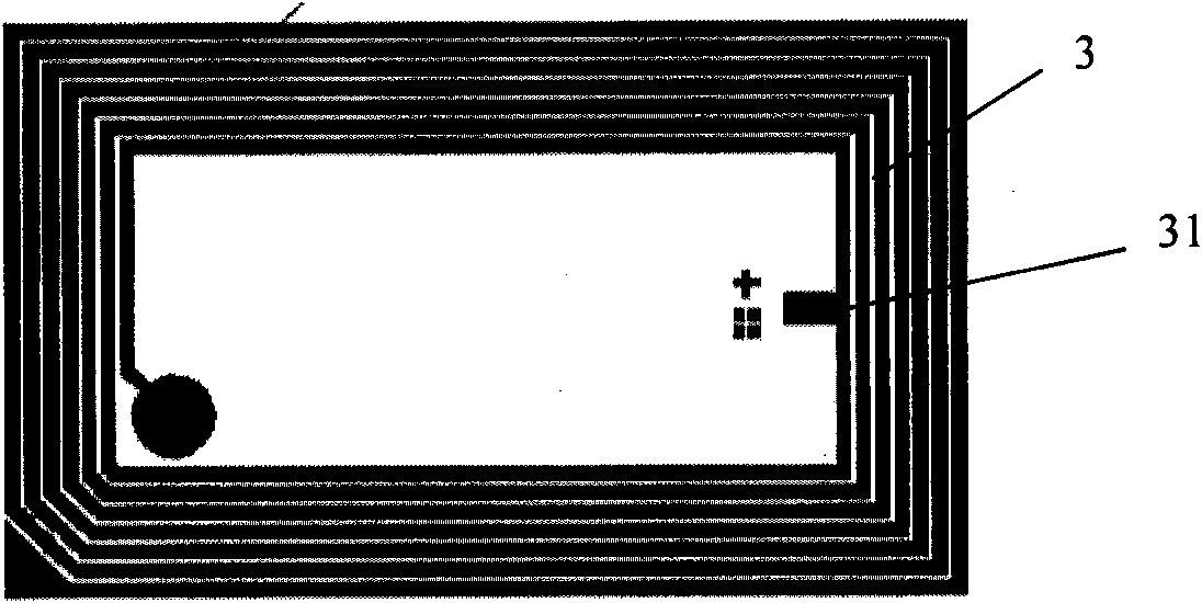
[0039] Please see attached figure 1 As shown, the printed circuit board with radio frequency identification and the manufacturing method thereof of the present invention include a printed circuit board 1, a radio frequency identification chip 2, a radio frequency identification antenna 3 and a conductive glue 4; the radio frequency identification chip 2 is arranged on the printed circuit board 1 Above, the radio frequency identification antenna 3 is printed on the printed circuit board 1, and the antenna pin 31 is arranged on one side of the radio frequency identification antenna 3, and the conductive adhesive 4 can be anisotropic conductive adhesive, and the conductive adhesive 4 is arranged on the radio frequency identification chip 2 and the radio frequency identification chip 2. Between the identification antennas 3, the antenna pin 31 of the radio frequency identification antenna 3 is tightly connected to the connection port of the radio frequency identification chip 2, an...


PUM


Abstract

The invention discloses a printed circuit board with a radio frequency identification, comprising a printed circuit board, a radio frequency identification chip, a radio frequency identification antenna and conductive adhesive, wherein the radio frequency identification chip is arranged on the printed circuit board; the radio frequency identification antenna is printed on the printed circuit board; an antenna pin is arranged at one side of the radio frequency identification antenna; and the pin antenna is closely connected with a connecting port of the radio frequency identification chip by the conductive adhesive. The production method comprises the following steps of: firstly, printing the radio frequency identification antenna on the printed circuit board; secondly, coating an insulating layer at the part of the radio frequency identification antenna, which corresponds to a jumper wire; thirdly, printing the jumper wire and respectively connecting two ends of the jumper wire with the head and the tail of the radio frequency identification antenna; fourthly, coating the conductive adhesive on the antenna pin by adhesive dispensing equipment; fifthly, turning over the radio frequency identification chip to be connected with the antenna pin; sixthly, hot pressing the conductive adhesive and curing the conductive adhesive; and seventhly, testing the qualified rate. By using the invention, the labor cost can be saved, the work accuracy can be improved, the quality of products can be ensured, the processing can be accelerated and the logistics dynamic can be effectively tracked.

Description

technical field [0001] The invention relates to a printed circuit board and a manufacturing method thereof, in particular to a printed circuit board with radio frequency identification and a manufacturing method thereof. Background technique [0002] At present, a bolt-type radio frequency identification electronic tag in the prior art includes a body provided with a nut and a screw rod, and a cavity is provided on the body, and a chip COB assembly and an antenna assembly are arranged in the cavity, and the chip COB assembly includes a bottom layer PCB board, the copper-clad circuit layer arranged on the bottom PCB board and the IC chip arranged on the copper-clad circuit layer, the IC chip is connected with the copper-clad circuit layer by binding aluminum wires, and the antenna assembly includes the The soft magnetic rod and the antenna coil wound on the soft magnetic rod, the two ends of the antenna coil are soldered on the copper-clad circuit layer; the chip COB componen...

Claims


Application Information

Patent Timeline
Patent Type & Authority Applications(China)
IPC IPC(8): H05K1/16H05K1/18H05K3/00H01Q1/22H01R4/04G06K19/07
Inventor 冀京秋谭日升余舒浩刘卫宁胡爱君
Owner 上海中京电子标签集成技术有限公司
Learn More