
Clamp-type flange expansion sealed pipe joint

An expansion sealing and pipe joint technology, applied in the direction of flange connection, pipe/pipe joint/pipe fitting, through components, etc., can solve the problems of easy leakage, difficult installation, difficult completion, etc. Easy and fast installation, good sealing effect

Inactive Publication Date: 2011-04-13
陈西民
View PDF5 Cites 9 Cited by
  • Summary
  • Abstract
  • Description
  • Claims
  • Application Information

AI Technical Summary

Problems solved by technology

At present, there are basically the following types of common pipeline connection methods: one is direct brazing connection between pipelines, which is usually suitable for long-distance outdoor underground pipeline connection; the other is threaded pipe joint connection, which is usually suitable for small-diameter pipeline connection; the third is flange Pipe joint connection is usually suitable for pipeline inlet and outlet and valve connection. The flange pipe joint connection first needs to weld the pipe and the flange, and then connect the flange to the flange or to the valve flange or to the equipment flange. The flanges require a high degree of parallel contact, and the flange holes require a high degree of concentricity, otherwise the installation is difficult, especially when the flanges are sealed by flat gaskets, leakage is prone to occur, and it is difficult to ensure the sealing effect; while in mine roadway and subway construction, In environments with limited space such as emergency rescue, welding construction is difficult to complete, especially in special environments with flammable gases, welding construction is prohibited to ensure safety, so flanged pipe joints cannot be used
Still do not have a kind of ideal pipe joint that can overcome above-mentioned pipe joint defect at present

Method used


Image

  • Clamp-type flange expansion sealed pipe joint

Examples


Embodiment Construction

[0011] Below in conjunction with accompanying drawing, the present invention is described in further detail:

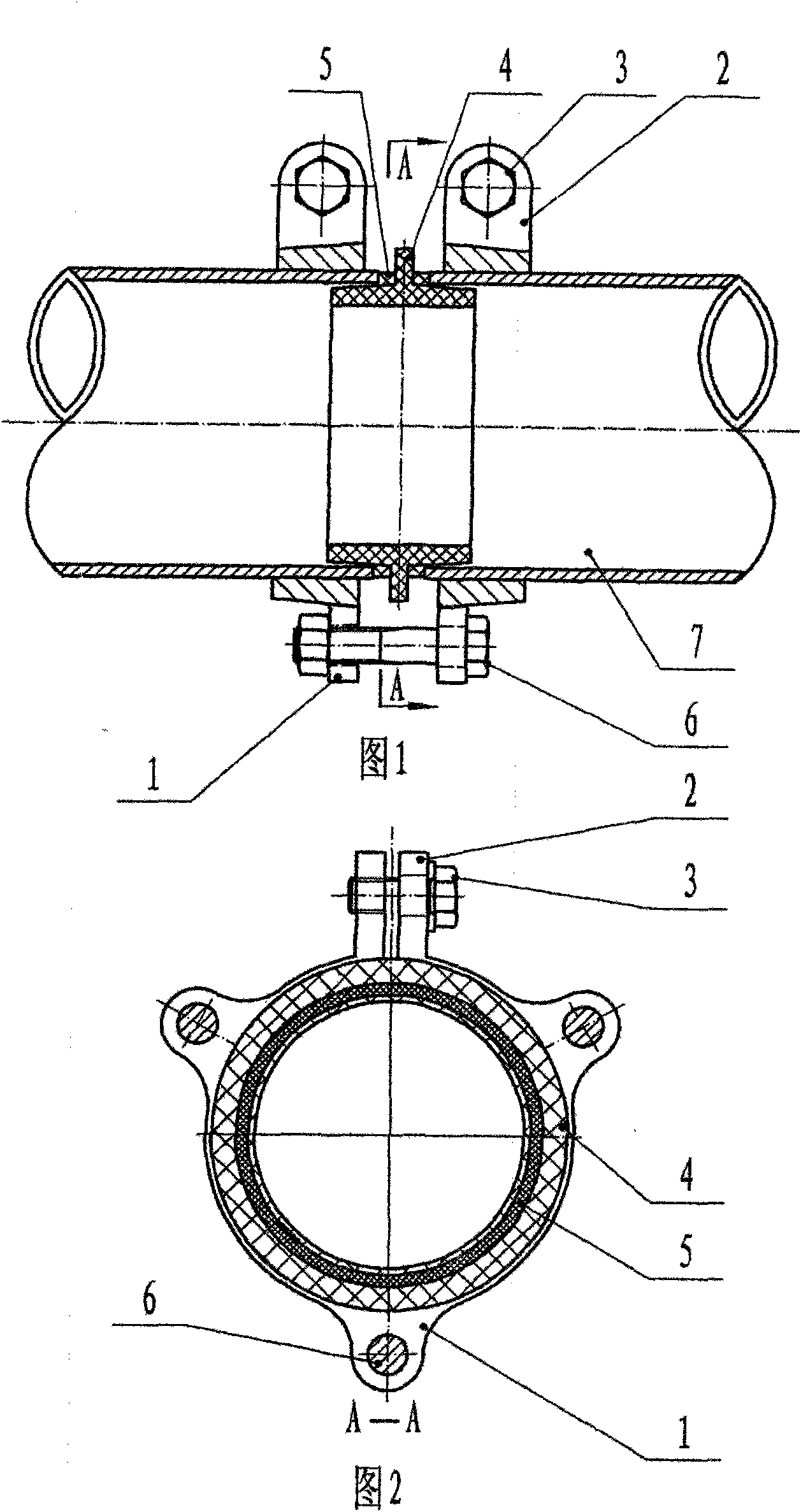
[0012] Clamp flanges (1) are installed on the outer edges of the ends of the two pipes (7) to be connected, and clamp heads (2) are arranged on the clamp flanges (1), and one side of the clamp heads (2) is The other side is an internal thread, and the clamp flange (1) is locked by the clamp bolt (3) through the through hole of the clamp head (2) and the internal thread. The sealing rings (5) are respectively installed on the conical surfaces on both sides of the step, and the sealing ring frame (4) equipped with the sealing rings (5) is respectively inserted into the inner ports of the two pipes (7) to be connected, and the two clamp flanges ( 1) Locked by the flange bolt (6), the sealing ring (5) is squeezed and expanded, the tapered surface of the sealing ring (5) is in close contact with the inner hole of the pipe (7), and the outer step of the sealing ring (5) is ...


PUM


Abstract

The invention discloses a clamp-type flange expansion sealed pipe joint, which does not need welding, is connected rapidly, has high sealing performance and is safe and reliable. In the technical scheme, clamp flanges are locked at the outer edges of the end parts of pipelines to be connected respectively; sealing rings are arranged on conical surfaces on both sides of sealing ring frames respectively; the sealing ring frames are inserted into the inner ports of the pipelines respectively so as to lock flange bolts; and the sealing rings expand under the action of extruding force, so that an inner loop and four end faces are fully sealed. The clamp flanges are connected with the pipelines through clamp bolts, the pipelines are connected with one another through flange bolts and the extruded and expanded sealing rings are tightly combined with the pipelines, so that high airtightness is realized; and the pipe joint can be installed conveniently and fast and can be connected reliably, is difficult to loose or fall off and is particularly suitable for limited construction spaces and special environments with inflammable gases.

Description

technical field [0001] The invention relates to a pipe joint for connecting pipelines, in particular to a clamp type flange expansion sealing pipe joint, which belongs to the technical field of pipeline processing. Background technique [0002] It is the easiest and safest way to transport water, fuel oil and gas through pipelines, but due to the limitation of the length of each pipeline, the pipelines must be connected. At present, there are basically the following types of common pipeline connection methods: one is direct brazing connection between pipelines, which is usually suitable for long-distance outdoor underground pipeline connection; the other is threaded pipe joint connection, which is usually suitable for small-diameter pipeline connection; the third is flange The pipe joint connection is usually suitable for the inlet and outlet of the pipeline and the connection of the valve. The flange pipe joint connection first needs to weld the pipe and the flange, and the...

Claims


Application Information

Patent Timeline
Patent Type & Authority Applications(China)
IPC IPC(8): F16L23/18F16L23/032
Inventor 陈西民
Owner 陈西民
Learn More