
Connecting rod of engine and making method thereof

A technology for connecting rods and connecting rods of engines, which is applied in the direction of connecting rods, connecting rod bearings, mechanical equipment, etc. It can solve the problems of many influencing factors and difficult control of cracking processing quality, and achieve the effect of large selectivity and easy tooth root strength

Inactive Publication Date: 2013-02-27
钟义
View PDF1 Cites 0 Cited by
  • Summary
  • Abstract
  • Description
  • Claims
  • Application Information

AI Technical Summary

Problems solved by technology

[0005] However, since the connecting rod cracking processing technology belongs to the precision processing technology, there are many influencing factors, such as connecting rod material, connecting rod forging process, connecting rod fracture section shape, initial crack groove and connecting rod cracking equipment, etc. Large impact, cracking processing quality is not easy to control

Method used


Image

  • Connecting rod of engine and making method thereof
  • Connecting rod of engine and making method thereof
  • Connecting rod of engine and making method thereof

Examples


Embodiment 2

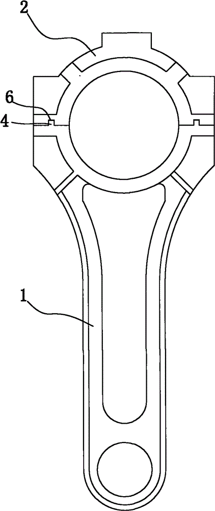
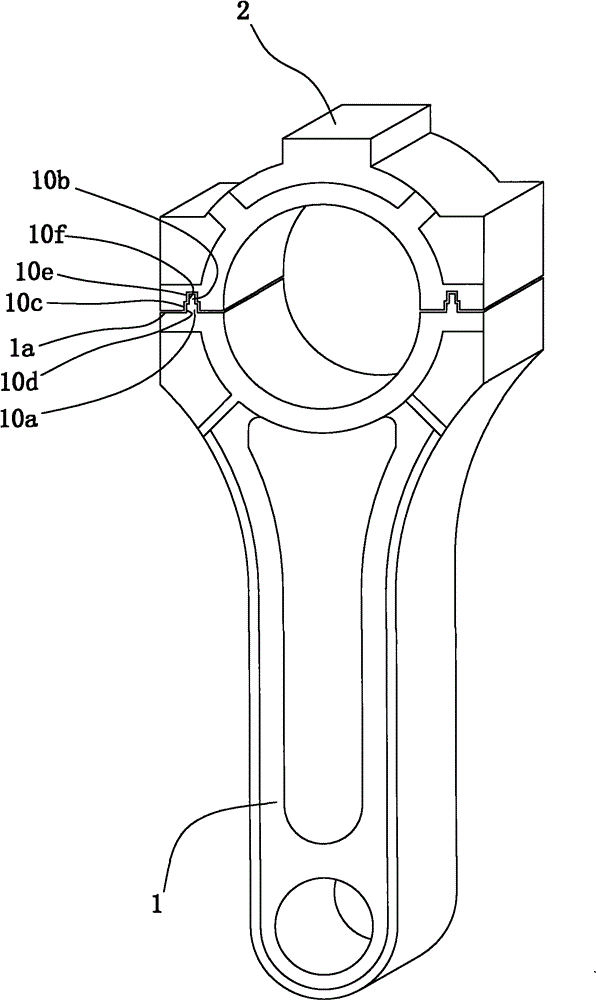
[0042] Such as Figure 6 , 7 As shown, an engine connecting rod includes a connecting rod body 1 and a connecting rod cover 2. The first mating surface 1a of the connecting rod body 1 is formed with a first groove group and a first groove group vertically intersecting with the first groove group. A convex tooth group, the first groove group includes two first grooves 3 arranged parallel to each other, the first convex tooth group includes two first convex teeth 4 arranged parallel to each other and shaped as a rectangle, the connecting rod cover 2 On the second mating surface 2a of the first groove group, a second convex tooth group consisting of rectangular second convex teeth 5 and a second concave tooth group matching with the first convex tooth group are formed. The second groove group composed of 6.

[0043] A method of producing the above-mentioned engine connecting rod, comprising the following steps: referring to Figure 8 , first take the initial connecting rod tha...

Embodiment 3

[0047] Such as Figure 11 , 12 As shown, a connecting rod for an engine includes a connecting rod body 1 and a connecting rod cover 2. The first mating surface 1a of the connecting rod body 1 is formed with a first groove group and a first groove group intersecting with the first groove group. Convex tooth group, the first groove group includes a first groove 3, the first convex tooth group includes a trapezoidal first convex tooth 4, the angle between the first groove 3 and the first convex tooth 4 is 60°, the second mating surface 2a of the connecting rod cover 2 is formed with a second convex tooth group consisting of a trapezoidal second convex tooth 5 that fits with the first groove group, and a second convex tooth group that is compatible with the first convex tooth group. The matched second groove group is composed of the second groove 6 .


PUM


Abstract

The invention discloses a connecting rod of an engine and a making method thereof. A connecting rod body and a connecting rod cover of the connecting rod are respectively provided with convex teeth and a groove in a crossing way, the convex teeth on the connecting rod body are matched with the groove on the connecting rod cover, and the groove on the connecting rod body is matched with the convex teeth on the connecting rod cover. In the method, a lug with a half part equal to the convex teeth and the other half part adapted to the groove is firstly cut from the initial connecting rod, then, another lug with a half part equal to the convex teeth and the other half part adapted to the groove is cut from the initial connecting rod in another direction, and arbitrary one cutting can halve the lug formed through the other cutting. Compared with the prior art, the invention has the advantages of higher locating accuracy, larger locating rigidity, convenience in disassembly and assembly, low manufacture cost and the like, changes a tooth form and a tooth groove amount, regulates an included angle between each tooth and each groove and an included angle of the tooth groove and a crankshaft axis, distributes X-direction and Y-direction locating intensity ratios, compensates a stress deformation error and provides a perfect scheme for processing an integral forging type connecting rod.

Description

technical field [0001] The invention belongs to the field of engine connecting rods, in particular to an engine connecting rod and a manufacturing method thereof. Background technique [0002] As the main component of force transmission, connecting rod is widely used in various power locomotives and is an important component of various engines. In the process of transmitting force, the connecting rod bears high periodic impact force, inertial force and bending force. This requires that the connecting rod should have high strength, toughness and fatigue performance. At the same time, because it is an important moving part of the engine, it requires high reliability and durability. With the development of the automobile industry, the demand for connecting rods is increasing, and many different manufacturing processes have emerged. [0003] In the traditional manufacturing process, there are two methods for the manufacture of the connecting rod body and the connecting rod co...

Claims


Application Information

Patent Timeline
Patent Type & Authority Patents(China)
IPC IPC(8): F16C7/02B23H1/00
CPCF16C9/04
Inventor 钟树平
Owner 钟义
Learn More