
Constant voltage output charge pump circuit

A constant voltage output, pump circuit technology, applied in the direction of conversion equipment without intermediate conversion to AC, etc., can solve the problems of increasing circuit cost, increasing circuit complexity, increasing circuit area, etc.

Inactive Publication Date: 2011-04-06
UNIV OF ELECTRONICS SCI & TECH OF CHINA
View PDF3 Cites 18 Cited by
  • Summary
  • Abstract
  • Description
  • Claims
  • Application Information

AI Technical Summary

Problems solved by technology

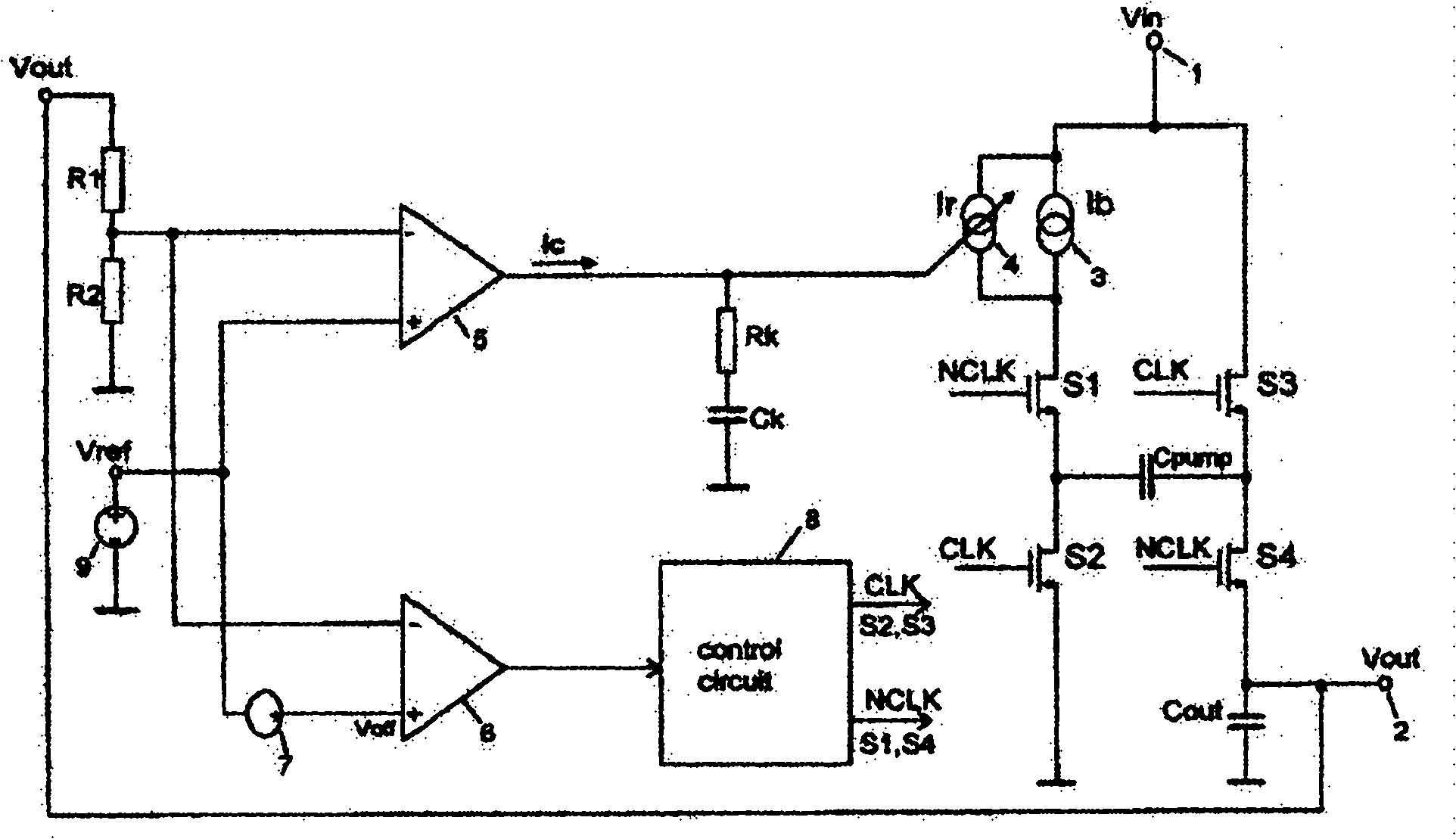
[0006] In the prior art, Erich Bayer et al. of Texas Instruments in the U.S. proposed a constant voltage output charge pump circuit (US 6,392,904B1), the circuit structure of which is shown in figure 1 As shown, the charge pump adopts a hybrid modulation mode combining linear control and cross-cycle control, which can achieve smaller output voltage ripple and higher efficiency, but its disadvantage is that the entire feedback circuit needs to use two high-gain Operational amplifier, and there are capacitors and resistors in the feedback circuit, which increases the complexity of the circuit, increases the area of ​​the circuit, and increases the cost of the circuit

Method used


Image

  • Constant voltage output charge pump circuit
  • Constant voltage output charge pump circuit
  • Constant voltage output charge pump circuit

Examples


Embodiment Construction

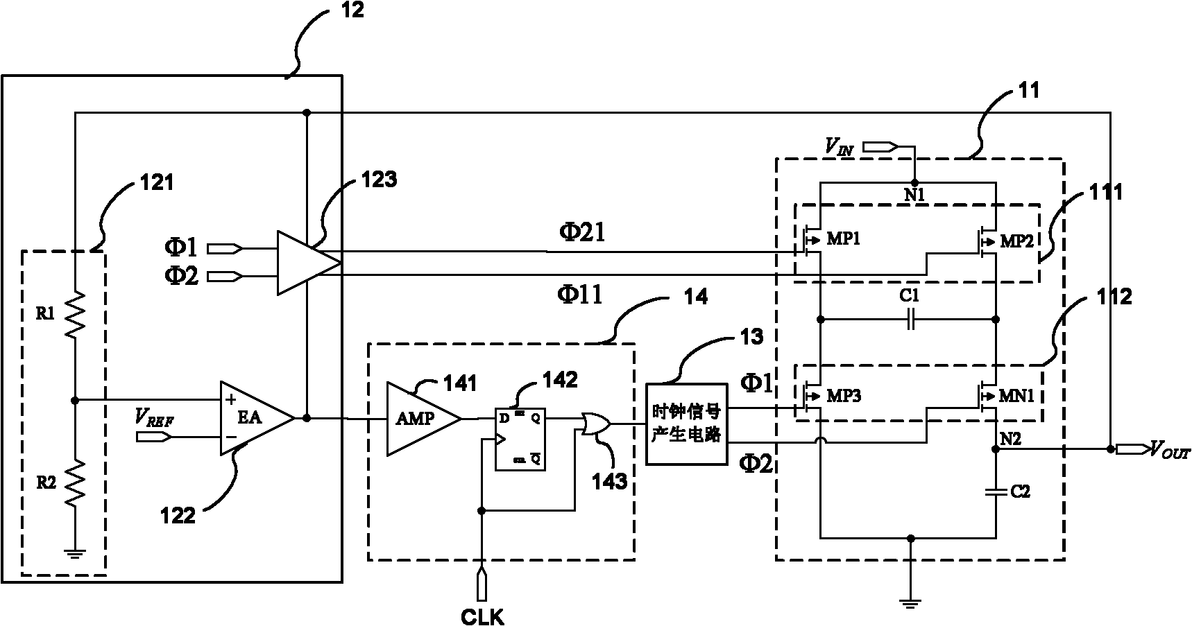
[0019] Further illustrate the present invention by embodiment in conjunction with accompanying drawing, image 3 Is a specific example in the present invention, the present invention is illustrated by its analysis, the structure of this example circuit is as follows

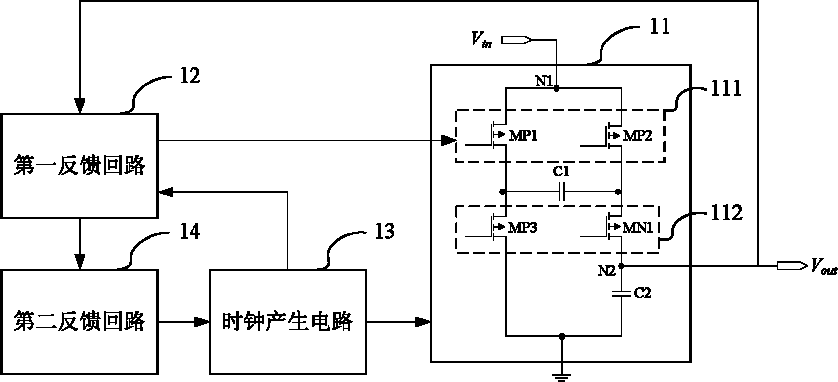
[0020] A pump circuit 11, which includes a bootstrap capacitor C1, an output voltage stabilizing capacitor C2, a switching device 112 for switching the first stage and the second stage of the pump circuit, and a switching device 112 for adjusting the second stage pump circuit output voltage regulator 111, wherein in the first stage the voltage V IN The bootstrap capacitor C1 is charged through the point N1. In the second stage, the bootstrap capacitor C1 charges the output voltage stabilization capacitor C2 through the point N2, and the output voltage V is generated at the point N2. OUT , coupled to the first feedback loop circuit at the same time;

[0021] A first feedback loop circuit 12, which circuit includ...


PUM


Abstract

The invention discloses a constant voltage output charge pump circuit. The circuit comprises a pump circuit, a clock generating circuit, a first feedback loop circuit and a second feedback loop circuit. The pump circuit comprises a switching device for switching clock signals when the pump circuit is switched to work between the first stage and the second stage and an adjusting device for adjusting the magnitude of the output voltage of the pump circuit of the second stage. The clock generating circuit is used for generating clock signals enabling the switching device to work. The first feedback loop circuit monitors the output voltage of the pump circuit to generate a corrected voltage to the adjusting device of the pump voltage so as to control the output voltage of the pump circuit. The second feedback loop circuit monitors the output voltage of the pump circuit to generate an enabling signal to the clock generating circuit so as to determine whether the pump circuit works and control the output voltage of the pump circuit. Therefore, the charge pump circuit can keep constant output voltage under the condition of variable input voltage or load so as to prevent the output voltage from changing together with the change of the input voltage or the load.

Description

technical field [0001] The invention relates to a charge pump circuit, in particular to a constant voltage output charge pump circuit. Background technique [0002] As a kind of power supply circuit, the charge pump circuit is based on the switched capacitor voltage bootstrap technology. Through different switched capacitor topologies, its output voltage can be any multiple of the input voltage. Compared with other types of power supply circuits, the advantages of charge pump circuits are mainly low cost, low electromagnetic interference (EMI), and high efficiency. [0003] A constant voltage output charge pump generally includes a control circuit and a pump circuit, which can control the pump circuit through the control circuit to stabilize the output voltage value of the pump circuit when the input voltage or load changes. [0004] There are mainly two control methods for the constant voltage charge pump circuit, which are linear control method and intercycle control meth...

Claims


Application Information

Patent Timeline
Patent Type & Authority Applications(China)
IPC IPC(8): H02M3/07
Inventor 于奇李靖徐振涛陈必江张军王一鹏
Owner UNIV OF ELECTRONICS SCI & TECH OF CHINA
Learn More