
Chemical mechanical polishing system

A technology of chemical machinery and polishing device, which is applied in the field of chemical mechanical polishing system, can solve the problems of a lot of time and energy spent on shutdown maintenance, troublesome CMP process monitoring, and affecting production efficiency, so as to reduce the probability of scratches, improve production efficiency, The effect of simplifying the process

Inactive Publication Date: 2011-04-06
SEMICON MFG INT (SHANGHAI) CORP
View PDF0 Cites 8 Cited by
  • Summary
  • Abstract
  • Description
  • Claims
  • Application Information

AI Technical Summary

Problems solved by technology

[0006] Therefore, in order to ensure the yield rate of the semiconductor manufacturing process, so that the CMP device will not become more and more dirty, it is necessary to perform periodic maintenance on the CMP system (Period Maintenance) to remove the crystallized particles condensed on the grinding head, This brings a lot of trouble to the process monitoring of CMP, and the constant downtime maintenance will spend a lot of time and energy, which seriously affects the production efficiency

Method used


Image

  • Chemical mechanical polishing system
  • Chemical mechanical polishing system
  • Chemical mechanical polishing system

Examples


Embodiment Construction

[0020] The present invention will be further described below in conjunction with specific embodiments and accompanying drawings, but the protection scope of the present invention should not be limited thereby.

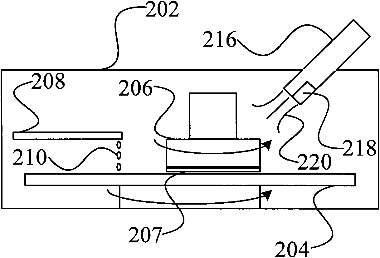
[0021] image 3 It is a schematic diagram of a chemical mechanical polishing system according to an embodiment of the present invention. Such as image 3 As shown, the chemical mechanical polishing system includes an outer cover 202 , a chemical mechanical polishing device inside the outer cover 202 , and an ultrasonic sprayer 216 for spraying into the outer cover 202 .

[0022] In this embodiment, the chemical mechanical polishing device includes a rotatable grinding pad 204; a grinding head 206 that turns to the same direction as the grinding pad 204, and a wafer 207 is adsorbed on the grinding head 206 by vacuum suction; The delivery pipe 208 for dripping the polishing liquid 210 onto the surface of the polishing pad 204 .

[0023] In this embodiment, the chemica...


PUM

PropertyMeasurementUnit
Diameteraaaaaaaaaa

Abstract

The invention provides a chemical mechanical polishing system, which comprises an outer housing and a chemical mechanical polishing device positioned in the outer housing, and also comprises an ultrasonic sprayer for spraying towards the inside of the outer housing. Based on the existing chemical mechanical polishing system, the ultrasonic sprayer for the medical filed is additionally arranged, so that the ambient humidity inside the outer housing is large enough, and a grinding liquid is not easy to adhere to a grinding head and condense into crystallized particles, or even if the crystallized particles are adhered to the grinding head, the crystallized particles are easy to wash off with deionized water in an environment with large enough humidity, thereby avoiding that the crystallized particles fall on a grinding pad to scratch the surface of a wafer. The chemical mechanical polishing system has the advantages of greatly reducing the probability of scratching the surface of the wafer in the chemical mechanical polishing process, simplifying the process and improving the production efficiency.

Description

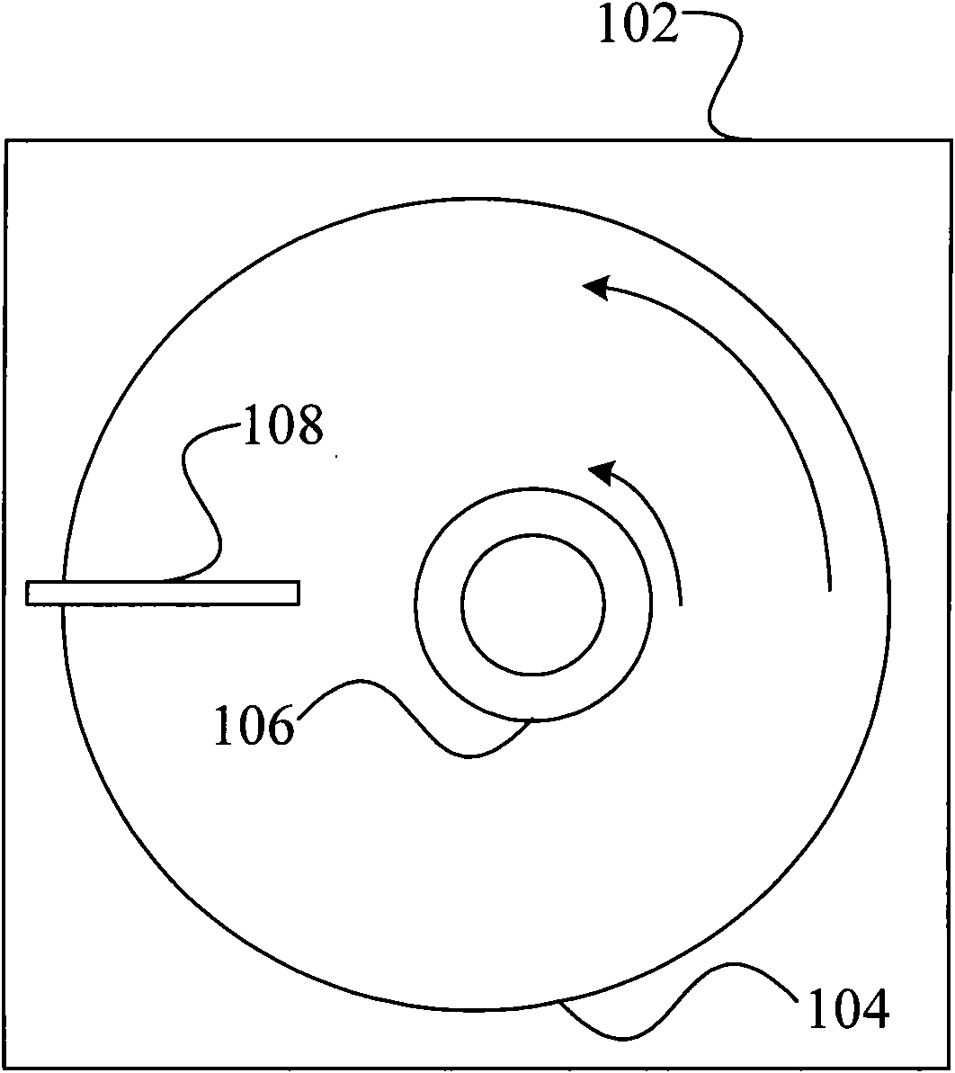
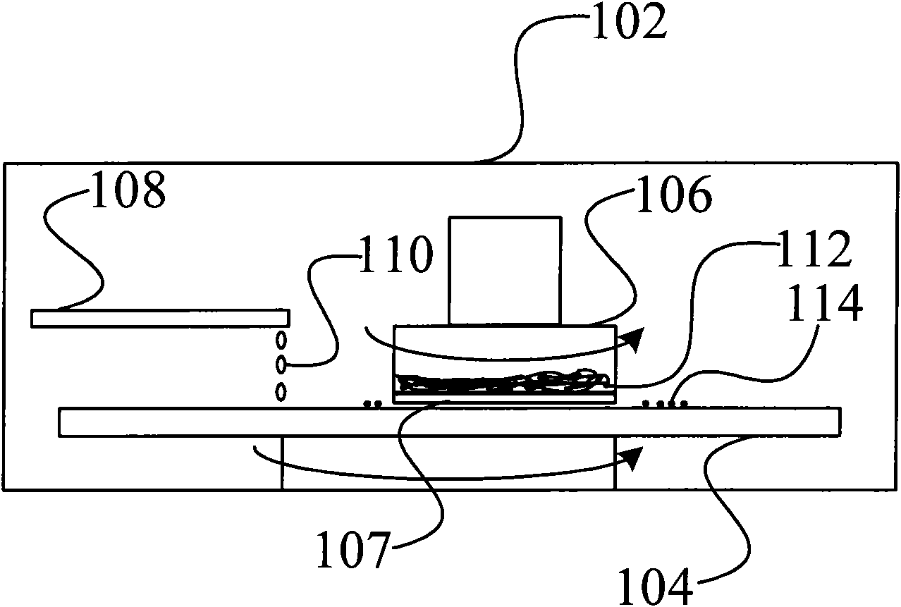
technical field [0001] The invention relates to the technical field of semiconductor manufacturing, in particular to a chemical mechanical polishing system. Background technique [0002] Chemical Mechanical Polishing (CMP) is an essential process link in the VLSI manufacturing process, and it is also one of the crucial processes that determine the yield of the final product. [0003] figure 1 is a schematic diagram of a prior art CMP system, figure 2 For such figure 1 Cross-sectional view of the CMP system shown. The CMP system includes an outer cover 102 and a CMP device inside the outer cover 102 , the CMP device includes a polishing head 106 , and a wafer 107 is fixed thereunder in a vacuum suction manner. After the conveyor 108 drips the slurry (slurry) 110 onto the surface of the polishing pad 104, the polishing head 106 rotates at a high speed in the same direction as the turning direction of the polishing pad 104, and the wafer 107 is pressed to the surface with ...

Claims


Application Information

Patent Timeline
IPC IPC(8): B24B37/04B24B29/02B24B57/02H01L21/02
Inventor 蒋莉李杰臧伟
Owner SEMICON MFG INT (SHANGHAI) CORP
Learn More