
Rear stop mechanism of plate shearing machine

A technology of backgauge and shearing machine, which is applied in the field of sheet metal processing, can solve the problems of backgauge deformation, backgauge error, and shear sheet size error, etc., and achieve the effect of strengthening the impact resistance

Inactive Publication Date: 2011-04-06
JIANGSU JIANGHAI MACHINE TOOLS GROUP
View PDF6 Cites 9 Cited by
  • Summary
  • Abstract
  • Description
  • Claims
  • Application Information

AI Technical Summary

Problems solved by technology

When the shearing tool holder moves up and down, the back gauge also moves up and down. At this time, the sheet material is close to the material stop plate. When cutting a narrow sheet, the phenomenon of squeezing the back gauge is easy to occur due to the shear distortion of the sheet material.
The size error of the sheet after shearing is caused, and the backgauge is deformed or even broken
In addition, when the general shearing machine adjusts the gap between the knife edges, the back gauge will move backwards along with the knife rest. Since the back gauge position display device is generally installed on the back gauge, and the back gauge moves with the upper knife rest produce a certain error
At the same time, in the process of use, the back gauge will be impacted by the plate. After long-term use, the connecting bolts will break in the general back gauge, and the size error of the sheared plate will be large, which may even cause the back gauge to fall off the tool holder. Down

Method used


Image

  • Rear stop mechanism of plate shearing machine
  • Rear stop mechanism of plate shearing machine
  • Rear stop mechanism of plate shearing machine

Examples


Embodiment Construction

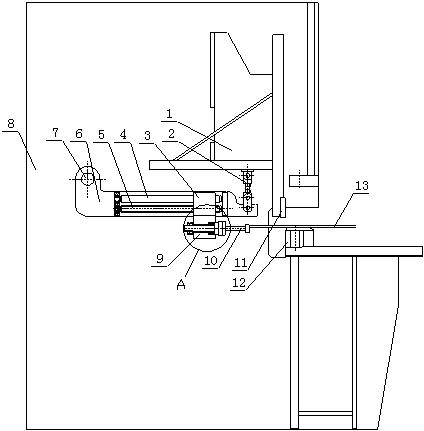
[0016] Such as figure 1 , 2 As shown, it is the back gauge mechanism of the shearing machine, including wallboard 8 and knife rest 1, a support shaft 7 is connected on the wallboard 8, a connecting rod 2 is connected below the knife rest 1, and the lower end of the connecting rod 2 can be The bracket 6 is detachably connected, and the other end of the bracket 6 is hingedly connected with the support shaft 7 . The light rod 4 and the lead screw 5 are arranged on the support 6 through bearings, the light rod 4 and the lead screw 5 are arranged in parallel, the lead screw 5 is screwed to the slide seat 3, the slide seat 3 is set outside the light rod 4, and the slide seat 3 is fixedly connected Hang tight seat 9, and hang tight seat 9 and connect material retaining plate 10. Among the figure, 11 is an upper blade, 12 is a lower blade, and 13 is a processing plate.

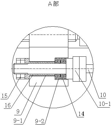
[0017] Such as image 3 As shown, an outwardly protruding step 10-1 is set on the baffle plate 10, a groove 9-2...


PUM


Abstract

The invention discloses a rear stop mechanism of a plate shearing machine, and relates to the technical field of plate processing, in particular to a plate shearing machine. The rear stop mechanism comprises a wallboard and a tool rest, wherein the wallboard is connected with a fulcrum shaft, a connecting rod is connected below the tool rest, the lower end of the connecting rod is detachably connected with a bracket, and the other end of the bracket is hinged with the fulcrum shaft; and the bracket is provided with an optical lever and a lead screw, the optical lever is arranged in parallel to the lead screw, the lead screw is connected with a sliding seat by screw thread, the sliding seat is sleeved outside the optical lever, the sliding seat is fixedly connected with a hanging seat, and the hanging seat is connected with a stop plate. The rear stop mechanism has the advantages that: 1, shift of the upper tool rest is not produced by adjusting the clearance of tool edges so as not to produce shift of a rear stopped material or cause plate size error; 2, a rear plate shearing size error is not produced by plate shearing distortion extrusion when a narrow plate is sheared; and 3, the joint of the bracket and the connecting rod is detachable, and the rear stopped material can be infinitely sheared after rotating 180 degrees, so the service range of the plate shearing machine is enlarged.

Description

technical field [0001] The invention relates to the technical field of plate processing, in particular to a shearing machine. Background technique [0002] At present, the back gauge of the shearing machine used at home and abroad is directly installed on the knife rest of the shearing machine. When the knife rest moves up and down when the shearing machine is working, the back gauge also follows the knife rest to do this movement. When the shearing tool holder moves up and down, the back gauge also moves up and down. At this time, the sheet material is close to the material stop plate. When cutting a narrow sheet, the phenomenon of squeezing the back gauge is easy to occur due to the shear distortion of the sheet material. . This will result in a size error of the cut sheet, and deformation or even breakage of the backgauge. In addition, when the general shearing machine adjusts the gap between the knife edges, the back gauge will move backwards along with the knife rest....

Claims


Application Information

Patent Timeline
Patent Type & Authority Applications(China)
IPC IPC(8): B23D15/06B23D33/00
Inventor 康铁强陈夕军丁建设许金建
Owner JIANGSU JIANGHAI MACHINE TOOLS GROUP
Learn More