
Node management method and control plane

A node management and control plane technology, applied in the field of optical communication, can solve problems such as interruption and inability to perform section switching

Inactive Publication Date: 2011-03-30
HUAWEI TECH CO LTD
View PDF2 Cites 7 Cited by
  • Summary
  • Abstract
  • Description
  • Claims
  • Application Information

AI Technical Summary

Problems solved by technology

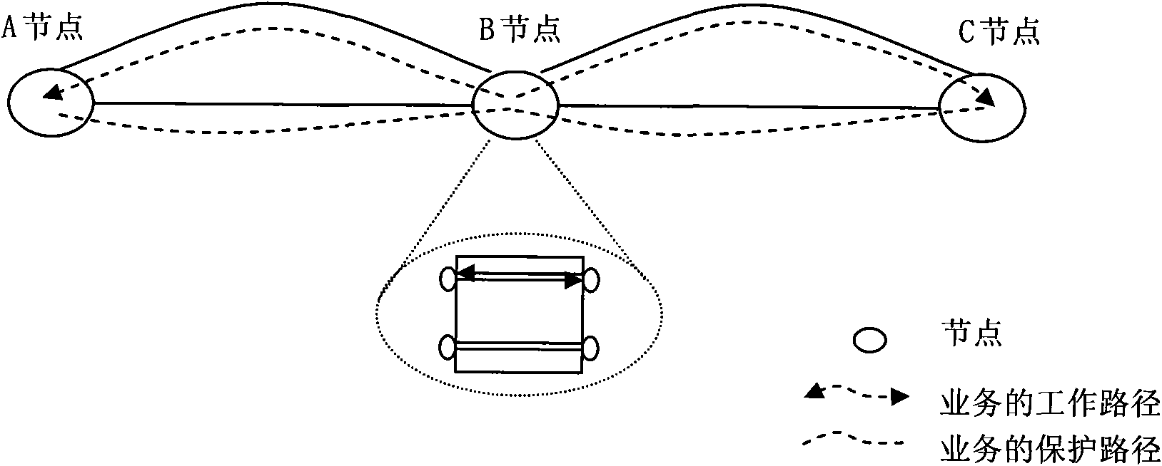
[0005] However, since the working path and the protection path in ASON create two pairs of two-way crossovers at the intermediate node B, the same service must use the working path or the protection path in the two paths at the same time, and section switching cannot be performed, for example: only If the optical fiber between node A and node B is interrupted, then node A and node B are switched to the protection path, and between node B and node C must also be switched to the protection path, not only between node A and node B sector switching
This may cause the following situation: the working path between node A and node B is interrupted, and the protection path between node B and node C is interrupted. If there are no other resources in the network for the business between node A and node C, node A Service interruption with node C
[0006] In the process of analyzing the existing optical transport network, the inventor found at least the following problems in the prior art: although the above solution can automatically create a new protection path, it cannot perform section switching

Method used


Image

  • Node management method and control plane
  • Node management method and control plane
  • Node management method and control plane

Examples


Embodiment 1

[0045] This embodiment provides a node management method, such as Figure 5 As shown, the method includes:

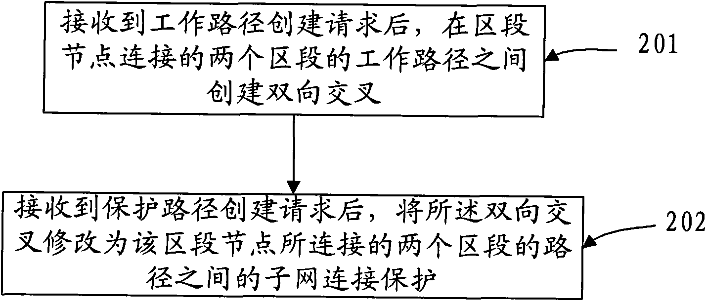
[0046] 501. After receiving a working path creation request, create a bidirectional intersection between the working paths of the two sections connected to the section nodes, and the working path creation request is sent to each node through control plane control. After the bidirectional crossover is created through the control plane on the section node, the section node can forward the service on the working path to the working path of the next section through the bidirectional crossover.

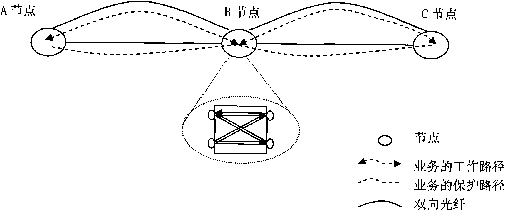
[0047] 502. After receiving a protection path creation request, modify the bidirectional crossover to subnet connection protection between paths of two sections connected to the section node, and the paths of the two sections include two zones The segment's working path and protection path, the protection path creation request is sent to each node through the control plane control....

Embodiment 2

[0091] It can also be applied to the following scenarios: the optical network carries optical layer services. Before the node management method and control plane in the embodiment of the present invention are applied, the optical layer service signals can be directly forwarded to the In the next section, an electrical relay is introduced in this embodiment, and the application Figure 5 and Figure 6 After corresponding to the node management method and the control plane, the section switching of the optical layer service can be realized. In the embodiment of the present invention, the electrical relay is implemented by back-to-back OTUs (wavelength conversion units). In this embodiment, after the optical layer service signal is crossed at the optical layer of the section node, it goes down to the electrical layer and is converted into an electrical signal in the electrical relay, and the electrical relay converts the transmitted electrical signal into an optical signal and s...

Embodiment 3

[0110] The scenario of the optical network in this embodiment is different from that in Embodiment 2. This embodiment includes multiple section nodes, such as Figure 13 As shown, nodes B and D in the figure are both section nodes, so that there are multiple sections between node A and node C, and section switching can be performed independently in each section. Four SNCPs are configured on nodes B and D through the control plane.

[0111] If the optical fiber between node A and node B is interrupted, only the section switching between node A and node B can be performed, and other sections do not need to be switched again. If the optical fiber between node B and node D is interrupted, section switching can only be performed between node B and node D. If the service requires dynamic rerouting, rerouting calculation is performed, and the specific calculation process is the same as that of Embodiment 1 and Embodiment 2.

[0112]The sections in all the above-mentioned embodiment...


PUM


Abstract

The invention discloses a node management method and a control plane, relates to the technical field of an optical network and can solve the problem the existing optical network can not simultaneously carry out span switch and automatic creation of new protecting paths. The node management method provided by the embodiment of the invention comprises the following steps: creating two-way cross between working paths of two spans connected at a span node after receiving a creation request of the working paths; and modifying the two-way cross to subnet connection protection between the paths of the two spans connected at the span node after receiving the creation request of the protecting paths, wherein the paths of the two spans comprise the working paths and the protecting paths of the two spans. The embodiment of the invention can calculate the new standby protecting paths by the control plane according to the corresponding algorithm, thereby ensuring that the exiting protecting paths can bear services through the standby protecting paths after faults exist in the existing protecting paths, and ensuring the normal operation of the services.

Description

technical field [0001] The invention relates to the technical field of optical communication, in particular to a node management method, a control plane, and an optical network switching management method and system in an optical communication network. Background technique [0002] The Optical Transport Network (OTN, Optical Transport Network) is a brand-new optical transport technology system, including the optical layer and the electrical layer, and has corresponding management and monitoring mechanisms and network survivability mechanisms for each layer of the network. In optical transport network applications, end-to-end services need to pass through a long fiber path with a high failure rate, so the optical transport network needs to have a service protection function. Generally speaking, the ASON (Automatically Switched Optical Network, Automatically Switched Optical Network) technology can be used to dynamically manage the working and protection paths of services. AS...

Claims


Application Information

Patent Timeline
IPC IPC(8): H04B10/08H04Q11/00H04L12/24
Inventor 罗贤龙林东乔胡明陈春晖
Owner HUAWEI TECH CO LTD
Learn More