
Control method and system for selectively compensating wattless power by active filter

A technology for compensating reactive power and source filters, which is applied in active power filtering, reactive power adjustment/elimination/compensation, harmonic reduction devices, etc. Achieve the effect of expanding the scope of applications, low hardware complexity, and improving real-time performance

Inactive Publication Date: 2011-03-30
CHANGSHA UNIVERSITY OF SCIENCE AND TECHNOLOGY
View PDF0 Cites 21 Cited by
  • Summary
  • Abstract
  • Description
  • Claims
  • Application Information

AI Technical Summary

Problems solved by technology

[0004] At present, the detection and separation methods in the industry have certain defects, and it is difficult to apply to the actual system with high real-time requirements: the FFT detection method can detect the amplitude and phase of each harmonic, but the calculation amount and delay bigger
The neural network detection method needs a lot of time to train the samples, and it is difficult to meet the real-time requirements
The harmonic detection method based on the principle of self-adaptive cancellation has good self-adaption ability, can track and detect well and has high precision, but the disadvantage is that the dynamic response is slow
The detection algorithm based on the theory of instantaneous reactive power can detect harmonics and reactive power separately, but the algorithm is relatively complicated
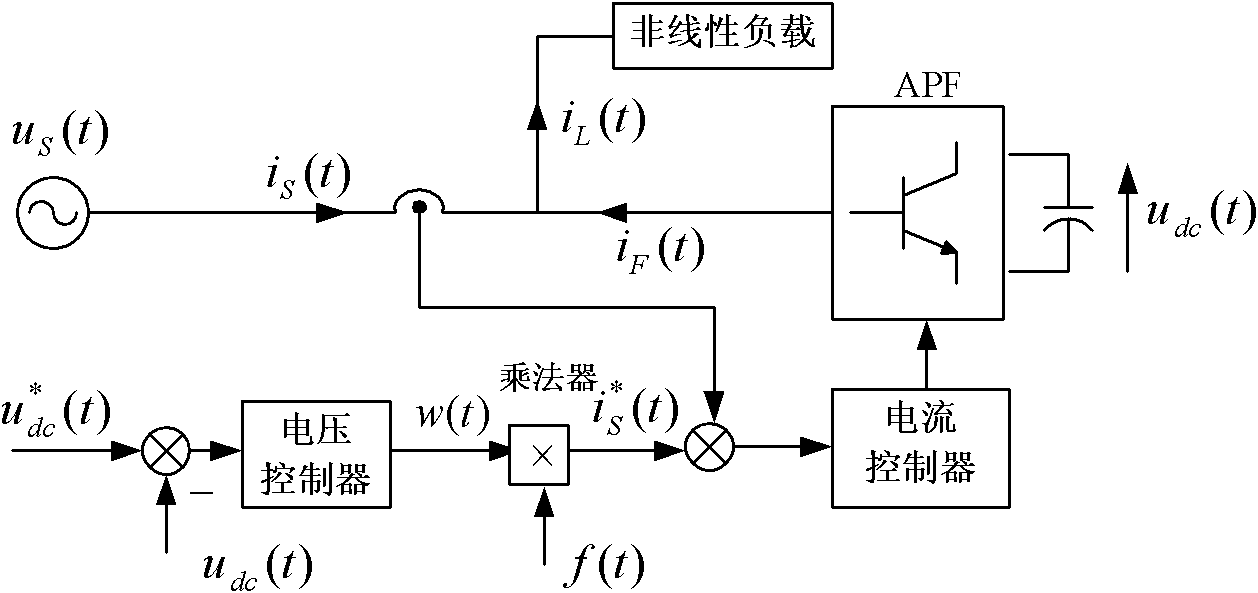
The active power detection algorithm based on the energy balance theory uses the multiplication of the control quantity of the voltage loop and the grid voltage factor to obtain the active current of the load. Compensate the reactive power of the grid
Therefore, when harmonic compensation is performed on a load with relatively large reactive power, it is easy to fail to filter out harmonics sufficiently, and the limit of the capacity of the active filter is reached.

Method used


Image

  • Control method and system for selectively compensating wattless power by active filter
  • Control method and system for selectively compensating wattless power by active filter
  • Control method and system for selectively compensating wattless power by active filter

Examples


Embodiment 1

[0062] Such as Figure 4 As shown, the harmonic sources include grid 1 and nonlinear load 2.

[0063] The single-phase active filter system applying the present invention includes a filter device 3 , an inverter device 4 and a control device 5 .

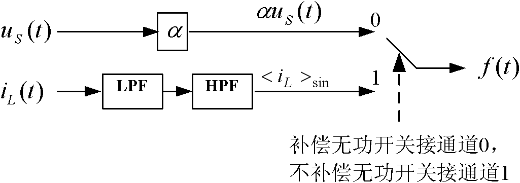
[0064] This example is an example of a single-phase active filter with DSP as the control core. The inverter device 4 of this example adopts a single-phase full-bridge structure; in order to effectively filter out high-order harmonics related to the switching frequency, the filter device 3 adopts a filter structure composed of inductance; the control device 5 is composed of a voltage loop controller 5.1 , limiting circuit 5.2 (DSP program implementation), filter 5.3 [the filter is image 3 LPf and hpf in , but in this example, the filter is realized by digital filter in DSP, no analog filter is used), switch 5.4, current loop controller 5.5, triangular wave modulation circuit 5.6, grid voltage detection circuit 5.7 , current detec...


PUM


Abstract

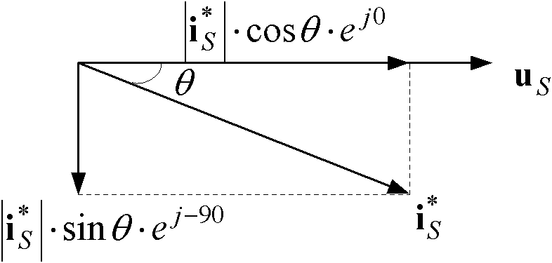
The invention discloses control method and system for selectively compensating wattless power by an active filter. The method comprises the following steps of: generating fundamental wave factors by electric network load current or electric network voltage; and then, multiplying the fundamental wave factors by the output of a voltage controller to generate control signals of the electric network current so that the active filter can selectively compensate the wattless power while filtering harmonic waves. The wattless compensation or wattless uncompensation can be selected through regulating the fundamental wave factors, the defect that the traditional wattful balance control method can only realize the simultaneous compensation of the harmonic waves and the wattless power but is not applicable to the large-capacitance wattless power load, the control method can be applicable to more application occasions, and in addition, the method of the invention does not need coordinate transformation and the phase locked loop and has , has simple algorithm and low hardware cost, thereby being capable of replacing the harmonic wave detection method based on the instantaneous wattless power theory in the active filter.

Description

technical field [0001] The invention belongs to the field of active power filters, and relates to a control method and system for selective compensation of reactive power by active filters. Background technique [0002] With the development of power electronics technology, a large number of non-linear loads have been put into use, and the problem of harmonic pollution in power grids has attracted more and more attention. Traditional passive filters are gradually being replaced by active power filters due to the disadvantages of only filtering specific sub-harmonics and easily resonating with the power grid. [0003] An important factor affecting the performance of the shunt active power filter (APF) is the acquisition of the current reference signal. Before determining the reference current, the harmonic and reactive current components should be separated according to the purpose of compensation. The purpose of compensation is different, and the decomposition method of cur...

Claims


Application Information

Patent Timeline
IPC IPC(8): H02J3/01H02J3/18
CPCY02E40/22Y02E40/40Y02E40/20
Inventor 唐欣姚成诚曾启明陈伟乐
Owner CHANGSHA UNIVERSITY OF SCIENCE AND TECHNOLOGY
Learn More