
Intelligent vaporization method of vaporized petroleum liquid and equipment thereof

An intelligent, petroleum-based technology, applied in combustion methods, liquid fuel supply/distribution, etc., can solve problems such as complex equipment structure, difficulty in standardized production and installation, unstable gas supply pressure, etc., and reduce equipment manufacturing and installation costs , better energy-saving effect, adjustable and controllable temperature

Inactive Publication Date: 2012-08-08
黄福台 +2
View PDF2 Cites 2 Cited by
  • Summary
  • Abstract
  • Description
  • Claims
  • Application Information

AI Technical Summary

Problems solved by technology

[0003] In view of the shortcomings of the above prior art, the applicant has proposed two invention patents, the patent numbers are: 00112399.8 and 200410066010.1, and the vaporized petroleum liquid vaporization equipment proposed by these two patents has the following defects: (1) equipment The cost is high, the gas supply is 50kg per hour, and the cost of each set of equipment is 70,000-80,000; (2) The medium (heat transfer oil) is used for heat transfer, the equipment structure is complex, and the design requirements are high, which must be carried out according to the specific conditions of each kiln. It is difficult to carry out standardized production and installation; (3) using heat transfer oil for heat transfer, because the quality of heat transfer oil is unstable, it will bring trouble to the operator, and heat transfer with heat transfer oil will cause serious delays, and the use of The air supply pressure is unstable, which complicates the operation; (4) The use of heat transfer oil for heat transfer, due to the unstable quality of heat transfer oil, also brings unsafety to the use of heat transfer oil for heat transfer, and the national safety caused by the quality of heat transfer oil The accident rate is very high, and in order to use the heat transfer oil safely, cumbersome control instruments are added

Method used


Image

  • Intelligent vaporization method of vaporized petroleum liquid and equipment thereof
  • Intelligent vaporization method of vaporized petroleum liquid and equipment thereof
  • Intelligent vaporization method of vaporized petroleum liquid and equipment thereof

Examples


Embodiment 1

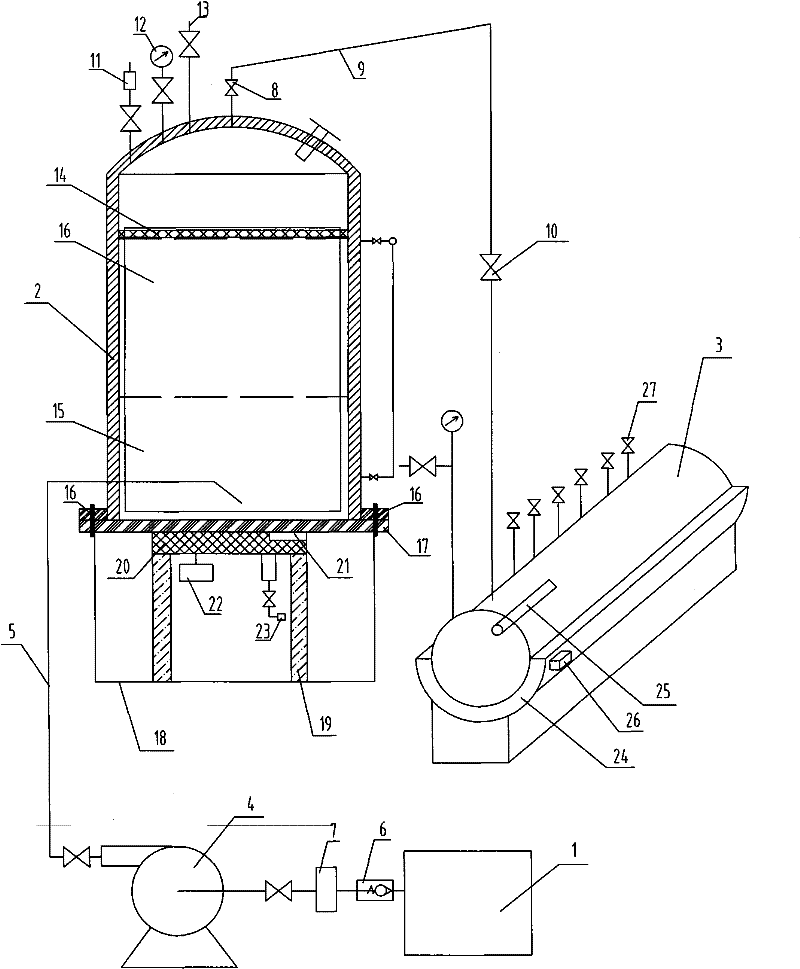
[0029] The intelligent vaporized petroleum liquid vaporization equipment of this embodiment has a structure such as figure 1 As shown, it includes a reserve cylinder 1, a vaporization tank 2 and a gas collecting pipe 3. The reserve cylinder 1 and the vaporization tank 2 are connected through a filling pipe 5 provided with a high-pressure liquid filling pump 4. The reserve cylinder 1 is connected through a one-way valve 6 and a filter Device 7 is connected with high-pressure filling pump 4. The vaporization tank 2 and the gas collecting pipe 3 are connected through a main air pipe 9 connected with an air supply valve 8 , and the gas supply valve 8 is connected with the gas collecting pipe 3 through an adjustable pressure reducing and stabilizing valve 10 . The upper part of the vaporization tank 2 is connected with a pressure sensor 11 , a pressure gauge 12 and an overpressure vent pipe 13 , and an anti-foaming net 14 is arranged at the upper part of the vaporization tank 2 . ...

Embodiment 2

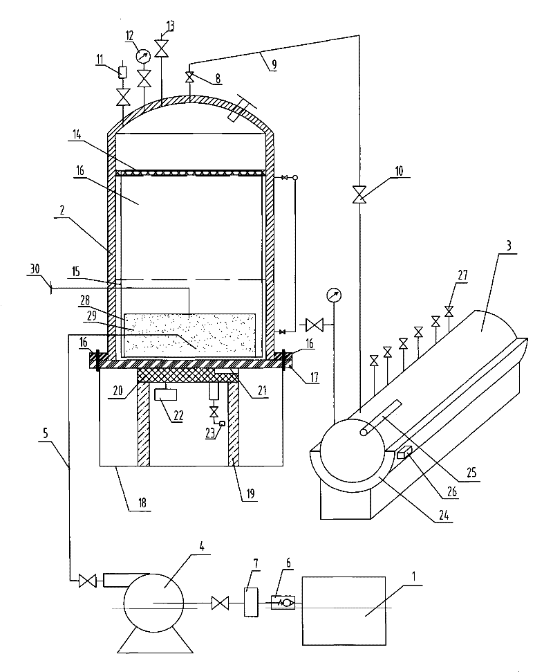
[0039] The intelligent vaporized petroleum liquid vaporization equipment of this embodiment has a structure such as figure 2 As shown, it includes a reserve cylinder 1, a vaporization tank 2 and a gas collecting pipe 3. The reserve cylinder 1 and the vaporization tank 2 are connected through a filling pipe 5 provided with a high-pressure liquid filling pump 4. The reserve cylinder 1 is connected through a one-way valve 6 and a filter Device 7 is connected with high-pressure filling pump 4. The vaporization tank 2 and the gas collecting pipe 3 are connected through a main air pipe 9 connected with an air supply valve 8 , and the gas supply valve 8 is connected with the gas collecting pipe 3 through an adjustable pressure reducing and stabilizing valve 10 . The upper part of the vaporization tank 2 is connected with a pressure sensor 11 , a pressure gauge 12 and an overpressure vent pipe 13 , and an anti-foaming net 14 is arranged at the upper part of the vaporization tank 2 . ...

Embodiment 3

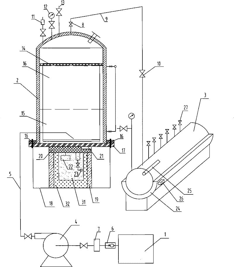
[0050] The intelligent vaporized petroleum liquid vaporization equipment of this embodiment has a structure such as figure 2 As shown, it includes a reserve cylinder 1, a vaporization tank 2 and a gas collecting pipe 3. The reserve cylinder 1 and the vaporization tank 2 are connected through a filling pipe 5 provided with a high-pressure liquid filling pump 4. The reserve cylinder 1 is connected through a one-way valve 6 and a filter Device 7 is connected with high-pressure filling pump 4. The vaporization tank 2 and the gas collecting pipe 3 are connected through a main air pipe 9 connected with an air supply valve 8 , and the gas supply valve 8 is connected with the gas collecting pipe 3 through an adjustable pressure reducing and stabilizing valve 10 . The upper part of the vaporization tank 2 is connected with a pressure sensor 11 , a pressure gauge 12 and an overpressure vent pipe 13 , and an anti-foaming net 14 is arranged at the upper part of the vaporization tank 2 . ...


PUM


Abstract

The invention relates to an industrial liquid vaporization method and equipment thereof, in particular to a vaporization method of vaporized petroleum liquid and equipment thereof. In the method, an electric heating chassis is used for heating the vaporized petroleum liquid in a vaporization tank; the heating temperature of the electric heating chassis is between 150 DEG C and 300 DEG C; an electric heating base is used for heating a gas collecting pipe; and the heating temperature of the electric heating base is higher than the vapor temperature of the vaporization tank by 10 DEG C to 20 DEGC. The equipment comprises a reservoir cylinder, the vaporization tank and the gas collecting pipe, wherein the lower part of the vaporization tank is provided with the electric heating chassis bonded with the bottom; the lower part of the gas collecting pipe is provided with the electric heating base bonded with the bottom; and the electric heating chassis and the electric heating base are both internally connected with a temperature sensor. In the invention, the electric heating chassis and the electric heating base are directly used for heating to avoid transferring heat through a medium; during heating, the electric heating base and the electric heating chassis are started only; after the temperature reach a set temperature, the electric heating base and the electric heating chassis can be conveniently controlled for stopping heating; the pressure and the temperature are adjustable and controllable; the heating efficiency is high; the heat transfer delay is slight; and the equipment is simplified.

Description

technical field [0001] The invention relates to an industrial liquid vaporization method and its equipment, in particular to a vaporized petroleum liquid vaporization method and its equipment. Background technique [0002] At present, energy-saving and environment-friendly fuels are the goals pursued by human society. C5 to C10 are by-products of the petrochemical industry, and their utilization rate has been very low. For many years, people have been trying to use one of carbon five to carbon ten as fuel gas raw materials, such as adding methanol, dimethyl ether, and ether to carbon five, and these components are neutral poisonous substances, which have been The country expressly prohibits it; there is also the transportation of refined carbon five and heating pipes side by side, using its heat to heat, so that carbon five can reach saturated vapor pressure, and can be fully burned when used, but due to uneven heating temperature, the degree of combustion is inconsistent, ...

Claims


Application Information

Patent Timeline
Patent Type & Authority Patents(China)
IPC IPC(8): F23K5/22
Inventor 黄福台肖杰王玖兴
Owner 黄福台
Learn More