Pressure machine

A mechanical and pressure technology, applied in the direction of presses, stamping machines, manufacturing tools, etc., can solve the problems of uneconomical and inability to change the slider action freely, and achieve the effect of easy management and easy operation of parts

Inactive Publication Date: 2013-10-16
KOMATSU SANKI
View PDF3 Cites 0 Cited by
  • Summary
  • Abstract
  • Description
  • Claims
  • Application Information

AI Technical Summary

Problems solved by technology

[0004] However, in the press machines described in Documents 1 to 3, the slider can only be driven by the slider movement determined by the shape of the slider and the swing lever, and the slider movement cannot be freely changed.
Therefore, for example, a press machine for drawing and shaping that drives the slider at a low speed near the bottom dead center, and a press machine for fine blanking that drives the slider at a relatively high speed near the bottom dead center need to be separately equipped. , which is uneconomical

Method used


Image

  • Pressure machine
  • Pressure machine
  • Pressure machine

Examples


Embodiment Construction

[0018] Hereinafter, an embodiment of the present invention will be described based on the drawings.

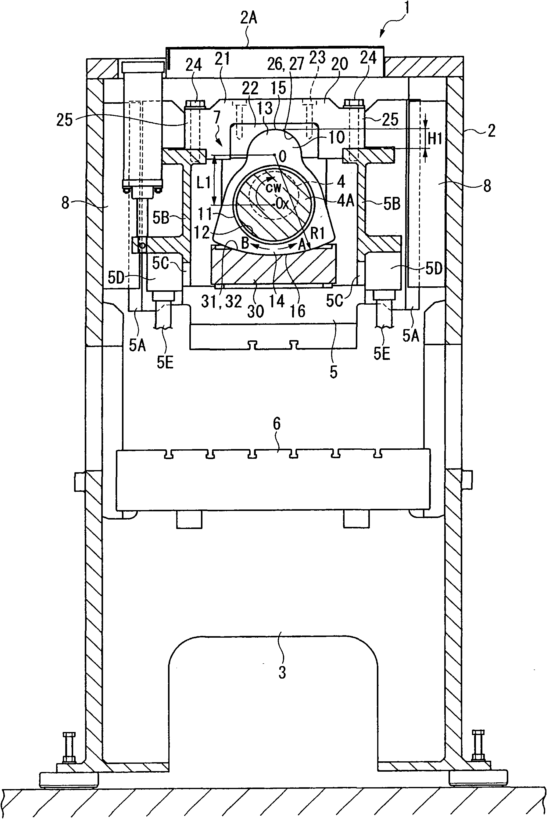
[0019] figure 1 Among them, the press machine 1 is a relatively small press machine with a pressure capacity ranging from tens of tons to tens of tons. Specifically, it includes: a frame 2 composed of a pair of metal plates erected on the left and right sides in the figure, A box-shaped base 3 composed of front and rear metal plates straddling the lower part of the frame 2, a shaft support part composed of front and rear metal plates (not shown) straddling the upper part of the frame 2, and an insertion shaft The main shaft 4 of the supporting part, the bottomed box-shaped slider 5 driven by the rotation of the main shaft 4 , and the backing plate 6 arranged on the upper part of the base 3 , and the rotation of the main shaft 4 is transmitted to the slider 5 through the swing rod drive mechanism 7 .

[0020] On the upper side of the frame 2, on the left and right inner wall s...


PUM


Abstract

A pressure machine includes a slide rod (5) to transfer rotation of a principal shaft 4) through a oscillating lever drive mechanism (7), which comprises: an oscillating lever (10) having an insertion through hole (12) sliding-free inserted by the principal shaft (4), an upper crown face (15) and a lower crown face (16) having an identical centre of curvature (O); a cap (20) sliding-freely supporting the upper crown face (15) by a crown face (27) having an identical curvature radius with the upper crown face (15) and dismounting-freely fixed on the slide rod (5); a block body (30) sliding-freely supporting the lower crown face (16) by a crown face (32) having an identical curvature radius (R1) with the lower crown face (16) and dismounting-freely fixed on the slide rod (5). By means of freely changing the oscillating lever (10), the cap (20) and the block body (30), a distance (L1) between a center (Ox) of the insertion through hole (12) and the centre of curvature (O) is changed, and a curvature radius (R1) of the lower crown face (16) is changed.

Description

technical field [0001] The invention relates to a press machine. Background technique [0002] Conventional press machines have known structures in which a swing rod drive mechanism for moving the slider up and down is provided in the slider (for example, Document 1: JP Unexamined Patent Publication No. 51-031975, Document 2: JP Unexamined Patent Publication 2006- 035230, Document 3: JP Unexamined Patent Application Publication No. 2008-296278). The swing rod driving mechanism of this kind of press machine includes a swing rod that is rotatably inserted through the eccentric part of the main shaft, and absorbs the displacement of the slider in the horizontal direction caused by the rotation of the main shaft through the swing of the swing rod, thereby only Drive the slider in the up and down direction. [0003] Since the drive mechanism of the swing rod is housed in the slide block, this kind of press machine can reduce the overall height compared with the press machine wi...

Claims


Application Information

Patent Timeline
Patent Type & Authority Patents(China)
IPC IPC(8): B30B1/26B30B15/06
CPCB30B1/26
Inventor 木下洋佐藤宏秀宫坂卓嗣
Owner KOMATSU SANKI
Why Eureka
Try Eureka