
Post-mix beverage dispenser with cooler

A cooler and post-mixing technology, applied in the field of post-mixing beverage preparation, can solve the problems of wasting energy, inefficiency, and increasing operating costs

Inactive Publication Date: 2011-02-23
IMI CORNELIUS UK
View PDF4 Cites 0 Cited by
  • Summary
  • Abstract
  • Description
  • Claims
  • Application Information

AI Technical Summary

Problems solved by technology

This is inefficient, wastes energy and increases operating costs

Method used


Image

  • Post-mix beverage dispenser with cooler
  • Post-mix beverage dispenser with cooler
  • Post-mix beverage dispenser with cooler

Examples


Embodiment Construction

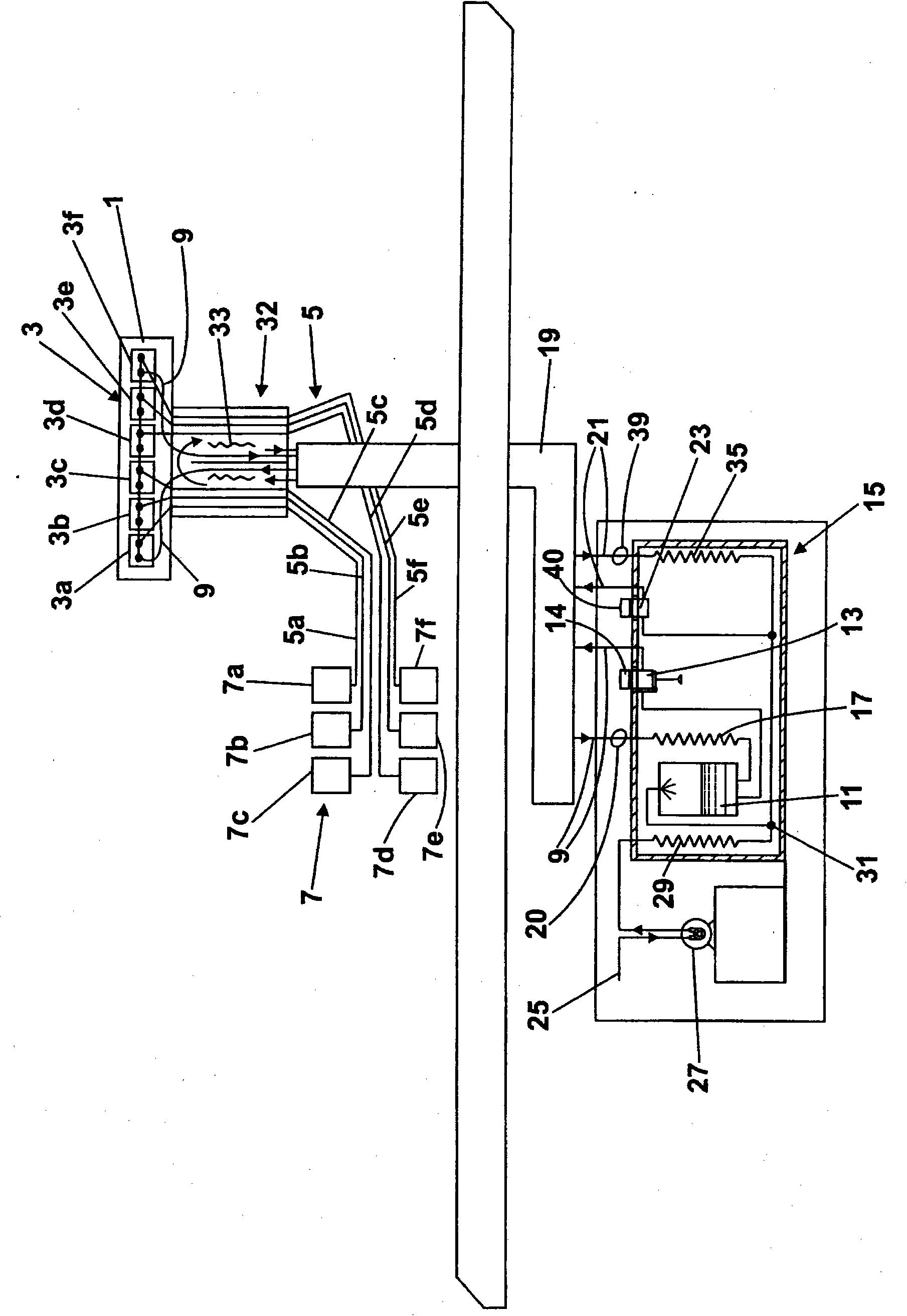
[0051] First refer to the attached figure 1 , which shows a post-mix beverage dispensing system comprising a manifold valve block 1 provided with a plurality of post-mix dispensing valves generally indicated by reference number 3 . In this embodiment, the integrated valve block 1 has six dispensing valves 3a, 3b, 3c, 3d, 3e and 3f, however, it can be understood that the number of dispensing valves can be selected according to requirements.

[0052] The dispensing valve 3 is connected by respective supply conduits, generally indicated by reference numeral 5 , to separate sources of concentrate, generally indicated by reference numeral 7 . In this embodiment, there are six supply lines 5a, 5b, 5c, 5d, 5e and 5f for each dispensing valve 3a, 3b, 3c, 3d, 3e and 3f respectively, and six concentrate sources 7a, 7b , 7c, 7d, 7e and 7f. However, it will be appreciated that such an arrangement is not required and that the number of supply lines and concentrate sources may vary depend...


PUM


Abstract

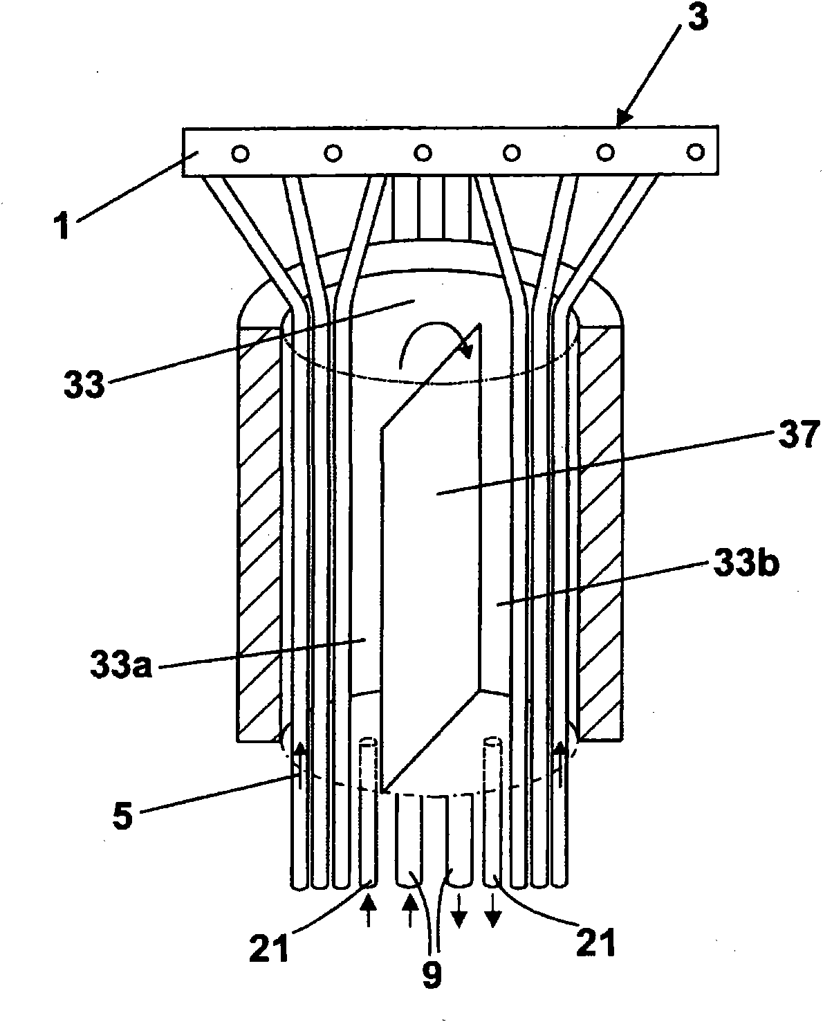
A beverage dispense system for a post-mix beverage dispenser in which the concentrate lines (5) are passed through a cooling module 33 within the dispenser. The cooling module (33) has a chamber (33a) that is flooded with coolant for heat exchange with the concentrate. The coolant is circulated in a line (21) between a remote cooler (15) and the cooling module (33) within an insulated sheath (19). Diluent is circulated in a line 9 between the cooler (15) and the beverage dispenser for mixing with the concentrate. In a modification, the coolant may comprise diluent for mixing with the concentrate. The concentrate lines (5) do not pass through the insulated sheath (19).

Description

technical field [0001] The present invention relates to beverage dispensing, and in particular but not exclusively to application in the field of soft drinks, usually dispensed after cooling. More specifically, the present invention relates to the dispensing of post-mixed beverages such as cola and flavored soda pops, wherein a concentrate such as fruit juice or flavor is mixed with a diluent, usually still or carbonated water, at the point of dispensing. Background technique [0002] The concentrate and diluent are usually mixed in the correct proportions in a post-mix dispensing valve to dispense the beverage at the dispensing outlet of the device, such as a countertop of a dispensing tower. The dispensing tower can have multiple outlets to dispense the same or different beverages. [0003] Beverage ingredients are usually transported from a remote ingredient source to the dispensing tower in separate supply lines. Typically, a diluent supply line runs through the cooler...

Claims


Application Information

Patent Timeline
Patent Type & Authority Applications(China)
IPC IPC(8): B67D1/08B67D1/00
CPCB67D1/0867F28D1/0213B67D1/0021B67D1/0884B67D1/0864
Inventor 克劳斯·维梅尔赫兹·阿尔滕巴赫
Owner IMI CORNELIUS UK
Learn More