Impact detection structure, impact detection system and method, and occupant protection system and method
一种碰撞检测、乘员保护的技术,应用在碰撞检测结构、碰撞检测系统和以及乘员保护系统和方法领域,能够解决部件数量大等问题
- Summary
- Abstract
- Description
- Claims
- Application Information
AI Technical Summary
Problems solved by technology
Method used
Image

Examples
no. 1 example
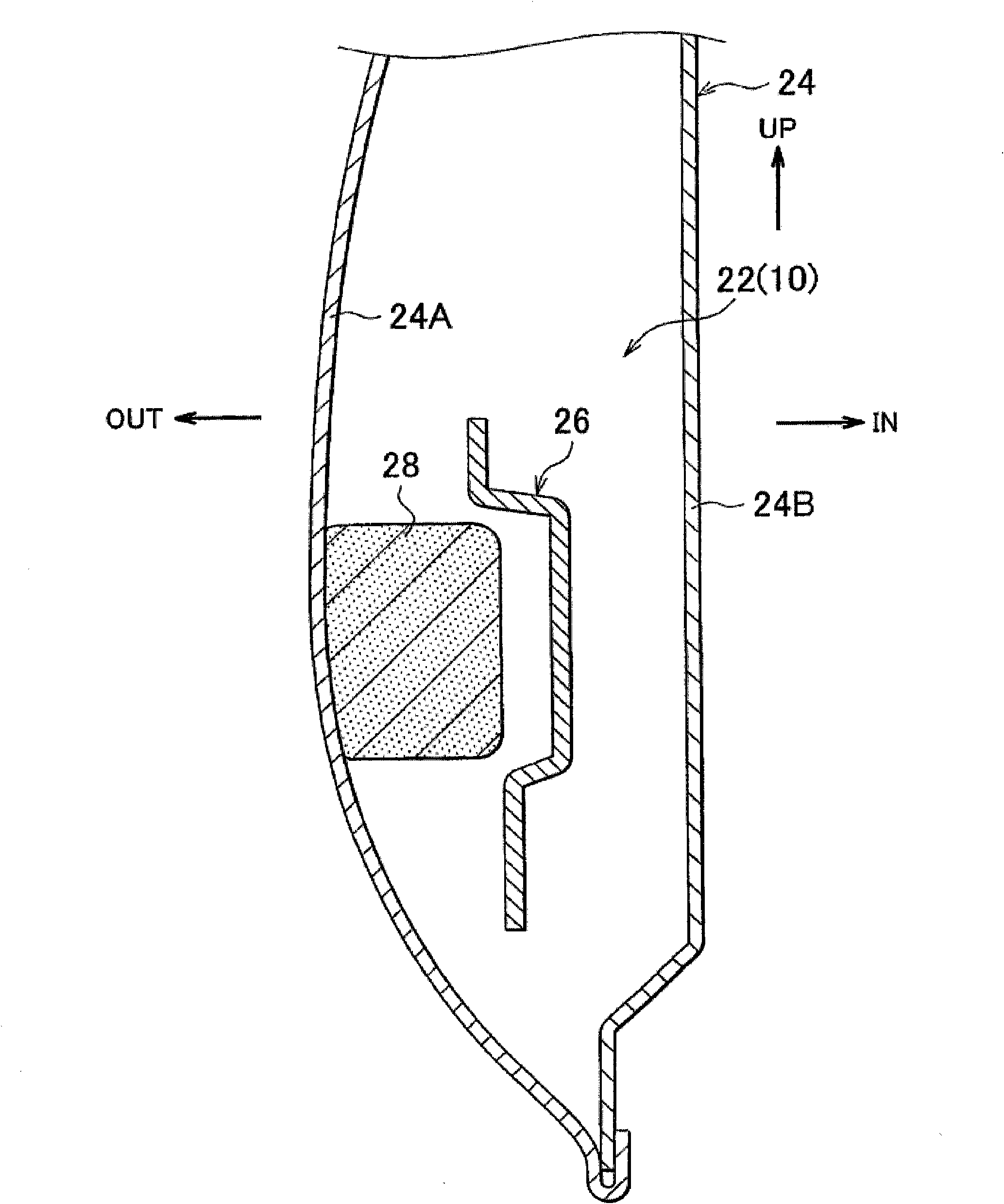
[0084] A side collision detection system 10 serving as a collision detection structure according to a first embodiment of the present invention will be described with reference to FIGS. 1 to 7 . First, a schematic configuration of a side collision-resistant occupant protection system 12 for protecting an occupant of an automobile 11 as a vehicle to which the side collision detection system 10 is applied will be explained, and then the side collision detection system 10 will be explained. In the drawings, arrows FR, UP, IN, and OUT indicate a forward direction relative to the vehicle, an upward direction relative to the vehicle, a laterally inward direction relative to the vehicle, and a laterally outward direction relative to the vehicle, respectively.
[0085] (Schematic structure of a side impact protection system)
[0086] FIG. 7 shows a schematic plan view of the front of the car 11 . As shown in FIG. 7 , the side collision protection system 12 includes side collision air...
no. 2 example
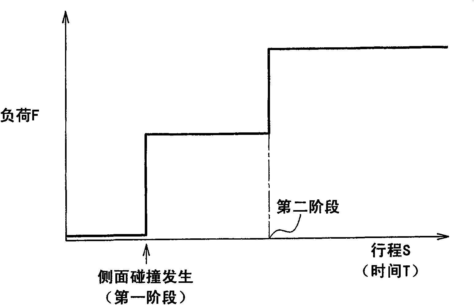
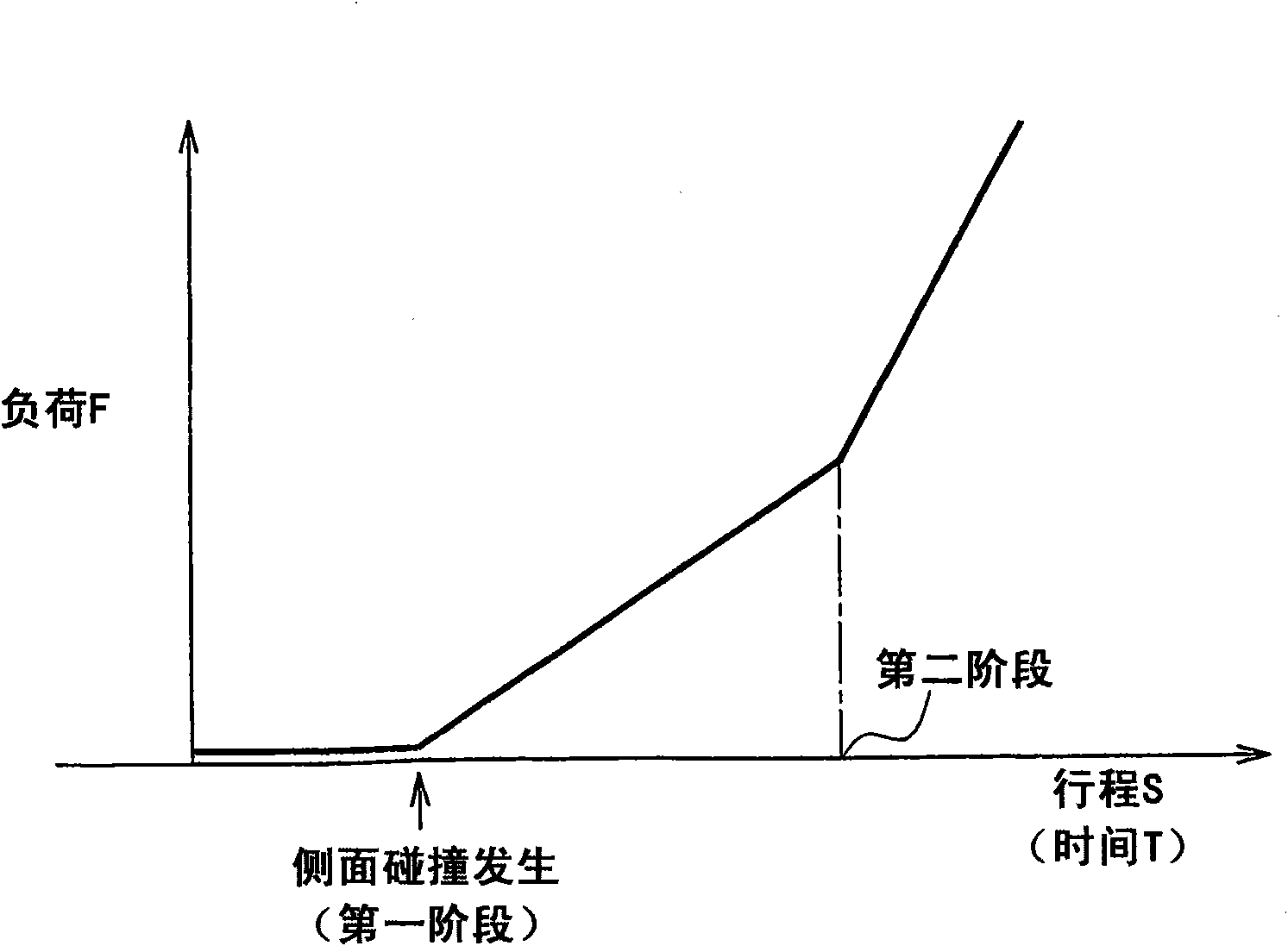
[0126] FIG. 20 shows the front of a car 11 using a side impact detection system 70 according to a second embodiment of the invention in a schematic plan view. As shown in the figure, the side impact detection system 70 differs from the side impact detection system 10 in that the side impact detection system 70 includes a two-stage load transfer structure 72 serving as a load transfer structure instead of the two-stage load transfer structure 22 .
[0127] The side collision detection system 72 transmits the load caused by the side collision to the side collision detection G sensor 20 arranged in the floor tunnel 18 in two stages. The two-stage load transmission structure 72 according to the second embodiment can be constructed such that, as shown in FIG. The stage load increases after a side impact and then the rate of change of the load decreases in the second stage input. A specific description is given below.
[0128] As shown in FIG. 15A , a two-stage load transmission s...
no. 3 example
[0152]24 shows in a block diagram corresponding to FIG. 3 a side impact detection system 100 and an occupant protection system 12 for protecting an occupant against a side impact including the side impact detection system 100 according to the third embodiment of the present invention. As shown in FIG. 24 , the side collision detection system 100 differs from the side collision detection system 70 according to the second embodiment in that instead of the side collision air safety device 15 and the CPU 32, the side collision detection system 100 includes: A safety air device 105 serving as an occupant protection device has a safety air device 102 for high load and a safety air device 104 for low load; and a CPU 106 serving as a collision determination section and a controller. Specifically, although not shown in the drawings, the side impact detection system 100 includes a two-stage load transfer structure 72 as the load transfer structure of the present invention or one of the t...
PUM
 Abstract
Description
Claims
Application Information
 - R&D
- Intellectual Property
- Life Sciences
- Materials
- Tech Scout
- Unparalleled Data Quality
- Higher Quality Content
- 60% Fewer Hallucinations
Browse by: Latest US Patents, China's latest patents, Technical Efficacy Thesaurus, Application Domain, Technology Topic, Popular Technical Reports.
© 2025 PatSnap. All rights reserved.Legal|Privacy policy|Modern Slavery Act Transparency Statement|Sitemap|About US| Contact US: help@patsnap.com