Swing bolster load testing method

A technology of load testing and bolster, applied in the direction of measuring force, measuring device, instrument, etc., can solve the problems affecting the fatigue reliability research of truck structure, inaccurate load spectrum of truck, inaccurate test structure, etc., and shorten the test work. The effect of reducing the number of cycles, reducing the steps of load calibration, and reducing the workload of the later stage

Active Publication Date: 2011-02-23
BEIJING JIAOTONG UNIV
View PDF1 Cites 1 Cited by
  • Summary
  • Abstract
  • Description
  • Claims
  • Application Information

AI Technical Summary

Problems solved by technology

[0011] Although the above-mentioned existing bolster load test methods are widely used in the fatigue reliability analysis of truck structures in my country, however, test workers also found that there is a problem that the test structure is not accurate enough in the process of work. The reasons are:
[0012] 1. Since it is difficult to paste strain gauges directly on the center plate of the bolster, the load value on the center plate can only be indirectly obtained through calibration tests. The process is complicated and there must be errors
[0013] 2. Use the strain gauge to measure the stress value, and obtain the load value by solving the equation, and its measurement accuracy is much lower than that of the load cell
[0014] 3. The strain value obtained by using the strain gauge measurement requires complicated post-work to convert it into the load value we need
[0015] Due to the existence of the above factors, the truck load spectrum obtained by the existing bolster load test method is not accurate enough, and even affects the research work on the fatigue reliability of the truck structure, which has become an urgent problem for those skilled in the art.

Method used


Image

  • Swing bolster load testing method
  • Swing bolster load testing method
  • Swing bolster load testing method

Examples


Embodiment Construction

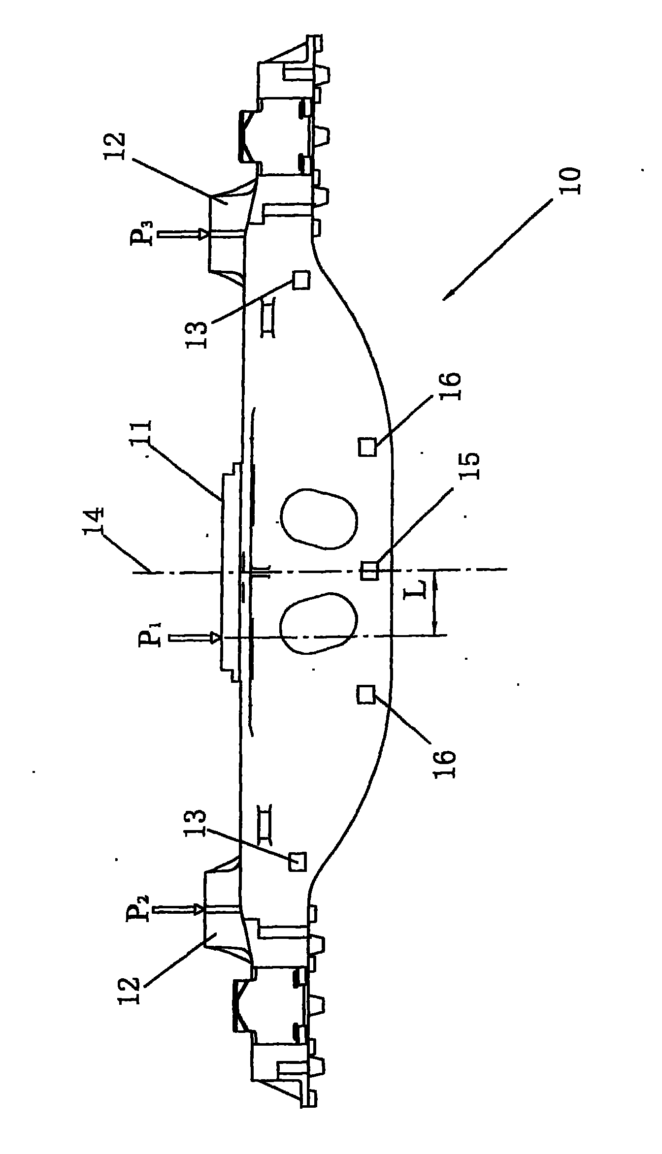
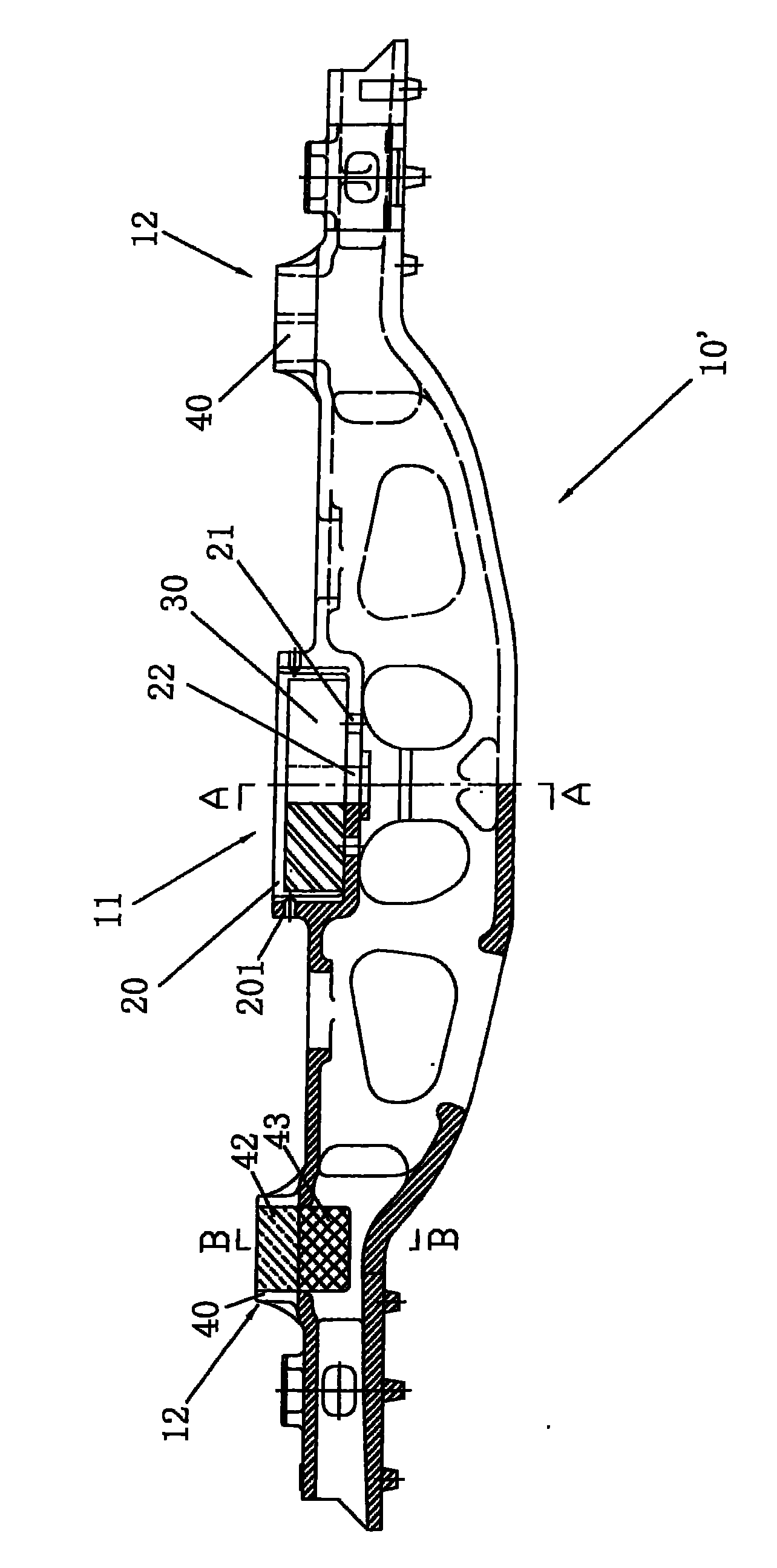
[0035] Such as figure 2 Shown is the bolster load test structure adopted by the present invention. The bolster 10' includes a center plate 11 and side bearings 12 arranged on both sides of the center plate 11. The improvements include:

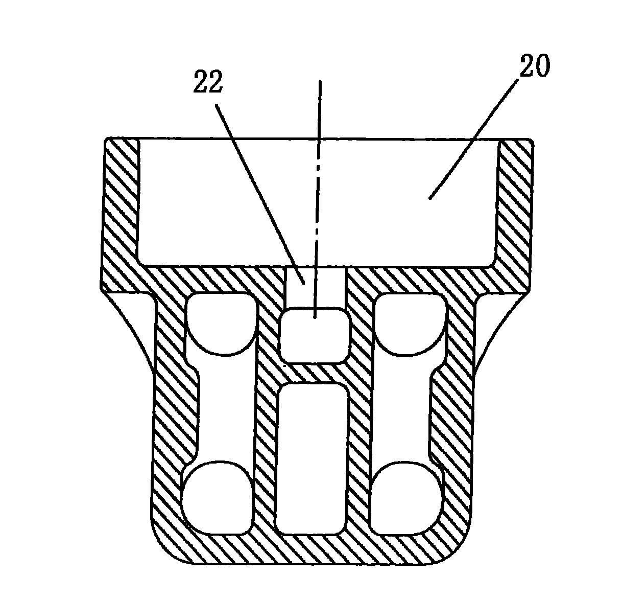
[0036] A center disc dynamometer 20 is processed at the center disc 11, and the center disc dynamometer 20 is a circular blind hole for a center disc load cell assembly 30 to be placed therein. On the side of the center disc dynamometer 20 There is a raised edge 201 to replace the lower center plate on the bolster 10'; when the center plate 11 of the bolster 10' is installed on the bogie, first the center plate load cell assembly 30 Place it on the bottom of the center disc dynamometer 20, then make the lower center disc of the car body fall into the raised edge 201, and press it above the center disc load cell assembly 30, and then use a pin The shaft passes through the lower center plate, the center plate load cell assembly 30 and the cent...


PUM


Abstract

The invention discloses a swing bolster load testing method. The method comprises the following steps of: 1) machining a centre plate force-measuring seat at a centre plate of a swing bolster, machining a side bearing force-measuring seat at each side bearing of the swing bolster, installing a centre plate force-measuring sensor component and a side bearing force-measuring sensor in the centre plate force-measuring seat and the side bearing force-measuring seat respectively, and installing the swing bolster on a bogie; 2) actually measuring during vehicle operation and acquiring signals measured by the centre plate force-measuring sensor component and the side bearing force-measuring sensor through a signal acquisition device; and 3) calculating a load-time history at the centre plate and the side bearing on the basis of the signals acquired by the signal acquisition device. Because centre plate force, the offset of the centre plate force and side bearing force are obtained in a way of direct measurement, the test precision of the centre plate force can be obviously improved; the steps for calibrating the load in a lab can be reduced; the period of test work is shortened; and human power and material resources are saved.

Description

[0001] This application is a divisional application. The original application was submitted to the Patent Office on February 11, 2009 with the patent number: 200910077441.0 and the invention title: "bolt load test structure and its test method". technical field [0002] The invention relates to a bolster structure of a train. Background technique [0003] Judging from the development of truck equipment technology in my country in the past ten years, the fatigue reliability of truck structure is a key factor restricting the improvement of truck equipment technology. If the fatigue crack occurs prematurely when the structure of the truck is significantly lower than the design life, the maintenance cost of the truck will remain high and the driving safety will be seriously endangered. Because the current structural strength design specifications and test standards for freight cars are not perfect, especially the lack of fatigue strength design specifications and test standards ...

Claims


Application Information

Patent Timeline
Patent Type & Authority Applications(China)
IPC IPC(8): G01L1/00
Inventor 孙守光李强刘志明谢基龙
Owner BEIJING JIAOTONG UNIV
Why Eureka
Try Eureka