


Quick Research
Generate reliable direction feasibility study reports for your R&D in just a few steps.

Technical Q&A
Discover and master advanced knowledge NOW. Basics, ideas, possibilities, all at once.

Find Solutions
As an expert in R&D theories, this can generate solutions to your technical problems instantly.

Evaluate Feasibility
Analyze your overall solution with one click, know your potential R&D risks in advance.

Monitor Landscape
Get weekly tech updates, stay abreast of the latest tech innovations and key insights.
Energy-saving numerical control screw press and control method thereof
A screw press and pressure technology, applied in the direction of presses, stamping machines, manufacturing tools, etc., can solve the problems of large impact force on the motor shaft, easy fatigue damage of the motor shaft, and difficult concentricity between the motor shaft and the gear shaft, etc., to achieve Facilitate flatness, ensure accuracy, and increase the effect of transmission torque
- Summary
- Abstract
- Description
- Claims
- Application Information
AI Technical Summary
Problems solved by technology
Method used
Image


Examples
Embodiment 2
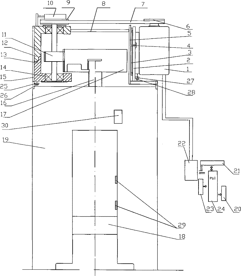
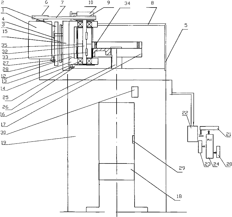
[0031] For a large-scale energy-saving numerical control screw press with a large pulley, the motor 1 and the pinion 31 are on the same side, which can effectively prevent the belt from being too long. The shape of the right vertical arm 5 of this kind of structure is different from embodiment 1, is straight.
[0032] In order to avoid the wear and tear of the pinion due to long-term work and affect the service life of the pinion, the pinion shaft can be composed of a pinion 31 , a transmission shaft 32 and a flat key 33 . There can be 2 or 3 flat keys 33. After a part of the pinion 31 is worn, the position of the pinion 31 can be rotatably adjusted to effectively increase the life of the pinion 31.
[0033] In order to improve production efficiency, a moment of inertia adjustment ring 34 is added at the end of the large gear 17, and the moment of inertia adjustment ring 34 is fastened to the end of the large gear 17 to adjust the moment of inertia and achieve the purpose of a...
Embodiment 3
[0035] In order to avoid wear and tear of the pinion due to long-term work and affect the service life of the pinion, the pinion shaft can be composed of a segmented pinion 35, a drive shaft 32 and a flat key 33. The split pinion 35 is connected with the power transmission shaft 32 through the flat key 33 in two sections. When used for a period of time, after a part of the segmented pinion 35 is worn out, the position of the segmented pinion 35 can be adjusted by exchanging the upper and lower parts, effectively increasing the life of the segmented pinion 35 . All the other are with embodiment 1.
[0036] In order to improve production efficiency, a moment of inertia adjustment ring 34 is added in the bull gear 17, and the moment of inertia adjustment ring 34 is fastened in the bull gear 17. The moment of inertia adjusting ring 34 is an integral type or a combined type, and the combined type is composed of multiple pieces.
PUM
 Abstract
Description
Claims
Application Information
 - R&D Engineer
- R&D Manager
- IP Professional
- Industry Leading Data Capabilities
- Powerful AI technology
- Patent DNA Extraction
Browse by: Latest US Patents, China's latest patents, Technical Efficacy Thesaurus, Application Domain, Technology Topic, Popular Technical Reports.
© 2024 PatSnap. All rights reserved.Legal|Privacy policy|Modern Slavery Act Transparency Statement|Sitemap|About US| Contact US: help@patsnap.com