
High-speed large-flow valve controlled hydraulic speed generator

A speed generator, large flow technology, applied in fluid pressure actuation devices, servo motor components, mechanical equipment, etc., can solve the problems of strict oil pollution, slow opening speed, low degree of automation, etc. Flow control, avoid secondary collision, achieve the effect of quick opening

Inactive Publication Date: 2011-02-16
WUHAN UNIV OF TECH
View PDF5 Cites 2 Cited by
  • Summary
  • Abstract
  • Description
  • Claims
  • Application Information

AI Technical Summary

Problems solved by technology

However, the traditional fluid directional control valve has a slow opening speed, and the maximum control flow cannot meet the requirements of high-speed and heavy-load impact crash tests.
When the traditional directional control valve needs to control a large flow rate, it often adopts a multi-stage (3-stage or even 4-stage) control method. The increase in the number of control stages leads to complex structure, large volume, and slow response speed.
Although the traditional electro-hydraulic servo valve has a fast response speed, it is expensive, requires high machining accuracy, and has strict requirements on the degree of pollution of the oil, and when the pressure loss is 10Mpa, the maximum controlled flow rate is 5500L / min
Secondly, gas has strong compressibility, and the unloading speed of the gas transmission device is much lower than that of the liquid. In order to avoid the secondary impact of the impact test, the existing impact test equipment powered by the pneumatic device adopts the Mechanical force limit measures, loud noise, low degree of automation

Method used


Image

  • High-speed large-flow valve controlled hydraulic speed generator
  • High-speed large-flow valve controlled hydraulic speed generator
  • High-speed large-flow valve controlled hydraulic speed generator

Examples


Embodiment Construction

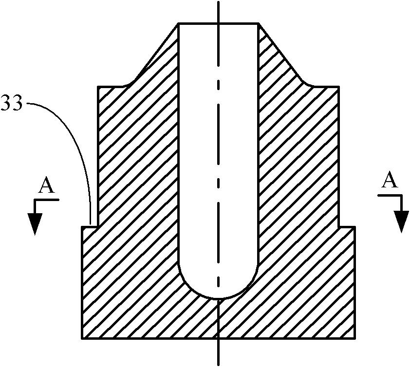
[0011] Such as figure 1 As shown, the present invention includes a pressure source, a high-speed and large-flow control device 38 and a hydraulic cylinder 37. The accumulator 30 is connected with the inlet passage 16 of the high-speed and large-flow control device, and the hydraulic cylinder 37 is connected with the outlet passage 19 of the high-speed and large-flow control device. Sealed to prevent leakage. The pressure source provides pressure fluid for the hydraulic cylinder 37, and the high-speed and large-flow control device 38 controls the movement speed of the piston assembly of the hydraulic cylinder 37.

[0012] The pressure source includes an accumulator 30 , an air charging valve 28 and a liquid charging valve 27 , and the air charging valve 28 and the liquid charging valve 27 are respectively connected to the accumulator 30 .

[0013] The high-speed and large-flow valve 38 includes a valve body 13, a piston spool 18, an adjustable flow valve 24, an on-off valve 23...


PUM


Abstract

The invention relates to a high-speed large-flow valve controlled hydraulic speed generator which comprises a pressure source, a high-speed large-flow control device and a hydraulic actuator, wherein the pressure source is connected with an inlet channel of the high-speed large-flow control device, the hydraulic actuator is connected with an outlet channel of the high-speed large-flow control device, and the connections are sealed to prevent leakage; and the high-speed large-flow control device can control the movement speed of a piston of the hydraulic actuator so as to adjust the test speed of impact collisions. The pressure difference between an upper cavity and a lower cavity of a piston valve plug is formed by means of the rapid release of pressure fluid, a large-size valve plug is quickly opened, and a larger flow is controlled by a smaller flow. The hydraulic energy of a power source is instantly converted into mechanical energy by means of the quick opening of a large-flow valve, so the difficulties of quick release of large energy and low reaction speed of the traditional large-flow valve in a project are overcome. A discharge circuit arranged in the hydraulic actuator realizes quick release of fluid pressure in a working cavity so as to avoid the oscillation of a piston assembly and the secondary collision of a test piece. The high-speed large-flow valve controlled hydraulic speed generator is applicable to high-speed heavy-load strong collision impact tests of electromechanical equipment, electronic products and various mechanical and construction structures.

Description

technical field [0001] The invention relates to a hydraulic speed generator for converting hydraulic energy into mechanical energy, in particular to a hydraulic speed generator for realizing the conversion of hydraulic energy into mechanical energy in a short stroke moment. technical background [0002] The requirements to improve the performance of electromechanical equipment, electronic products and various mechanical and architectural structures against external shocks such as explosions, earthquakes, collisions, and shock loads caused by aircraft take-off and landing have driven the development of shock test devices in the direction of heavy loads and high speeds. However, due to the limitation of the energy storage method and the huge size of the traditional drop, the gravitational potential energy of the pendulum or the potential energy of the spring, the room for expansion is very small, and it cannot even meet the high-speed and heavy-load crash impact test. The use ...

Claims


Application Information

Patent Timeline
Patent Type & Authority Applications(China)
IPC IPC(8): F15B15/08F15B13/04
Inventor 王贡献胡志辉胡勇
Owner WUHAN UNIV OF TECH
Learn More