Pathogenic microorganism aerosol pollution colony monitoring system

A pathogenic microorganism and monitoring system technology, which is applied in the system field of monitoring multiple pathogenic microorganism aerosol pollution groups at the same time, can solve the problems of personal safety and hazards of experimenters, and achieve accurate and reliable monitoring results, small size, and few gas path connections Effect

Active Publication Date: 2012-02-08
QINGDAO ZHONGRUI INTELLIGENT INSTR +1
View PDF0 Cites 0 Cited by
  • Summary
  • Abstract
  • Description
  • Claims
  • Application Information

AI Technical Summary

Problems solved by technology

In the past, air pollution monitoring systems were based on a single microbial sampler, which could only monitor the data of one point at a time, and the experimenters had to do it on-site. Potential hazards to personal safety are high and are not a good representation of the true outcome of an area's microbiological environment

Method used


Image

  • Pathogenic microorganism aerosol pollution colony monitoring system
  • Pathogenic microorganism aerosol pollution colony monitoring system
  • Pathogenic microorganism aerosol pollution colony monitoring system

Examples


Embodiment 1

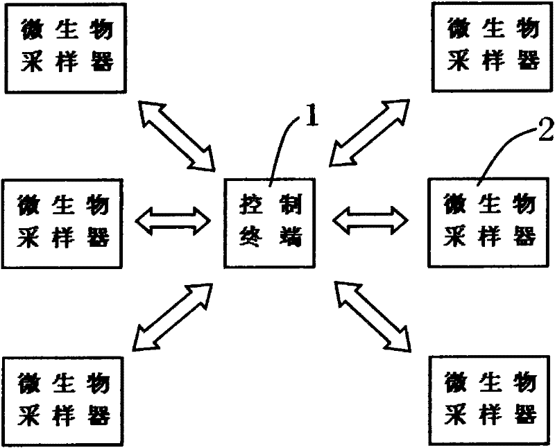
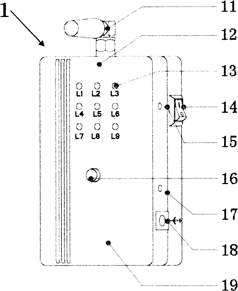
[0038] see Figure 1 to Figure 4 with Figure 6 to Figure 10, which includes a control terminal 1 and at least one microbial sampler 2, the internal wireless module 12 of the control terminal 1 and the wireless radio frequency module 228 of the microbial sampler 2 perform mutual data transmission through wireless transmission The control terminal 1 includes an antenna 11, an internal wireless module 12, a working indicator light 13, a power switch 14, a power indicator light 15, a start / stop button 16, a charging indicator light 17, an external power interface 18 and an internal high-energy lithium battery 19, and the antenna 11 is located on the top of the control terminal, the internal wireless module 12 is located in the casing of the control terminal, the antenna 11 is connected to the output end of the internal wireless module 12, the working indicator light 13 is located on the upper part of the front panel of the control terminal, and the power switch 14 is located on t...

Embodiment 2

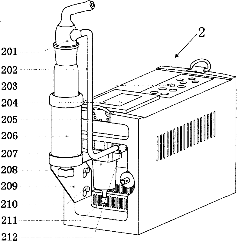
[0042] see Figure 1 to Figure 2 and Figure 5 to Figure 10 , the pathogenic microorganism aerosol pollution group monitoring system is basically the same as the implementation example 1, the difference is that: the sampling head is a secondary Anderson sampling device, and the secondary Anderson sampling device 217 is fixed on the sampling bracket by a star nut. Connect the air path at the gas outlet of the secondary Anderson sampling device, and connect it to the gas inlet of the microbial sampler. There are 9 indicator lights 13 above, and 9 microbial samplers. The working indicator lights 13 Divided into upper, middle and lower rows, the upper row is numbered L1, L2, L3 from left to right; the middle row is numbered L4, L5, L6 from left to right; the lower row is numbered from left to right They are L7, L8, L9; the states of L1-L9 respectively correspond to the working states of the first to ninth microbial samplers.

[0043] The principle of the present invention is as ...


PUM


Abstract

The invention relates to the technical field of the combination of environment monitoring and wireless control, in particular to a system capable of simultaneously monitoring a plurality of pathogenic microorganism aerosol pollution colonies. The system is characterized by comprising a control terminal and at least one microorganism sampler, and data transmission between a wireless module inside the control terminal and a radio frequency module of the microorganism sampler is performed in a wireless transmission mode. In the invention, a wireless networking technology is utilized to realize multipoint sampling with multiple samplers at the same time, one control terminal in a certain distance is used for unified control, and the problem of real-time, intelligent and multi-place acquisition is solved. The invention has the advantages that the system is easy to carry, small in size, wider in control range and farther in control distance, the control is more real-time, gas circuit connections are fewer, the suction of sampled gas is more stable, the separation of gas in water is more complete, a monitoring result is accurate and reliable, and better personal safety can be ensured by utilizing the system to monitor personnel.

Description

technical field [0001] The invention relates to the technical field of environmental monitoring, in particular to a system capable of simultaneously monitoring multiple pathogenic microorganism aerosol pollution groups. Background technique [0002] There are various microorganisms in the air. These microorganisms have a great relationship with our living environment. The sampling and analysis of microorganisms are becoming more and more important to us. The previous air pollution monitoring systems were based on a single microbial sampler, which could only monitor the data of one point at a time, and the experimenters had to do it on site. There are significant potential hazards to personal safety and are not a good representation of the true outcome of an area's microbiological environment. Contents of the invention [0003] In order to solve the above problems, the present invention adopts wireless networking technology to realize multi-point sampling of multiple sampl...

Claims


Application Information

Patent Timeline
Patent Type & Authority Patents(China)
IPC IPC(8): C12M1/36C12M1/26
Inventor 李劲松何春雷李娜杨晓平郭亮
Owner QINGDAO ZHONGRUI INTELLIGENT INSTR
Why Eureka
Try Eureka