
Side-clamping and self-locking device for parts and use method thereof

A technology of self-locking device and parts, which is applied to workpiece clamping device, feeding device, positioning device, etc., can solve the problem that it takes a long time to rotate the handle several times, which does not meet the requirements of mass production, and the retraction and advance distance of the extrusion head is long. Over-extrusion or insufficient extrusion, etc., to achieve the effect of small occupied space, simple structure and improved production efficiency

Active Publication Date: 2012-05-09
江苏环宇钢构重工有限公司
View PDF0 Cites 0 Cited by
  • Summary
  • Abstract
  • Description
  • Claims
  • Application Information

AI Technical Summary

Problems solved by technology

But its disadvantages are: in order to make room for the clamping of the parts, the extrusion head retracts and advances a long distance, and the screw mechanism needs the handle to rotate several times when it takes a long stroke, which takes a long time and does not meet the requirements of mass production.
This method can satisfy quick clamping, but if retraction and self-locking are required, the handle must be moved to the limit position to make the connecting rod form a dead angle
In this way, the dimensional error due to part error or extrusion head wear will cause over-extrusion or under-extrusion

Method used


Image

  • Side-clamping and self-locking device for parts and use method thereof
  • Side-clamping and self-locking device for parts and use method thereof
  • Side-clamping and self-locking device for parts and use method thereof

Examples


Embodiment Construction

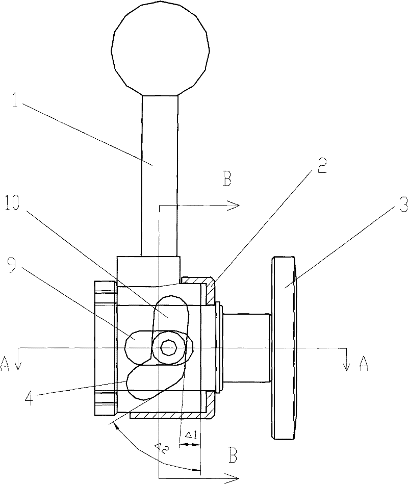
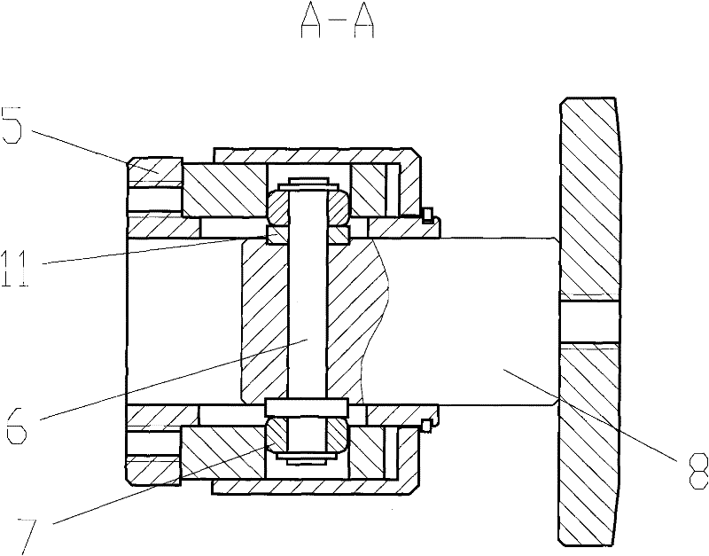
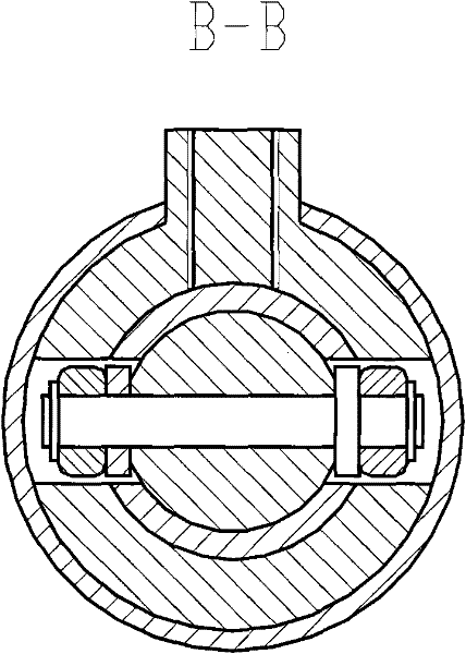
[0030] figure 1 The structure shown is a schematic diagram of the side clamping self-locking device for this kind of parts. figure 2 for figure 1 A schematic cross-sectional view of the A-A direction of the structure shown, image 3 for figure 1 Schematic cross-sectional view of the B-B direction of the structure shown. Depend on Figure 1-3 Combining the shown structures, it can be seen that the side clamping self-locking device for this kind of parts includes a positioning flange 5 fixed on the positioning fixture of the part to be processed, and the shaft end of the positioning flange 5 is provided with a step shaft 6 and a roller washer 11 The long groove 9 with clearance fit, the stepped shaft 6 and the roller washer 11 can slide or roll freely in the long groove 9, and a roller 7 is installed at both ends of the stepped shaft 6; the spiral grooved cylinder 4 is set on the positioning flange 5, and the spiral groove cylinder 4 is provided with two connected spiral c...


PUM


Abstract

The invention discloses a side-clamping and self-locking device for parts and a use method thereof. The self-locking device comprises a positioning flange (5) fixed on a part to be processed, a shaft end part of the positioning flange (5) is provided with an elongated slot (9) in clearance fit with a step shaft (6) and a roller gasket (11), and the step shaft (6) and the roller gasket (11) can feely slide in the elongated slot (9); a spiral groove drum (4) is sleeved on the shaft end of the positioning flange (5) and provided with two sections of spiral chutes (10) which are connected and have different spiral angles; and the step shaft (6) passes through the elongated slot (9), the spiral chute (10) and the front end of a telescopic shaft (8) and is fixed, and the end part of the telescopic shaft (8) is provided with a clamping disk (3). The device can meet the requirements on rapidly clamping the parts and guarantee the self-locking on the parts after the clamping, and a clamping and self-locking point can be automatically adjusted in a certain range, therefore, the requirement on massive production is favorably satisfied.

Description

technical field [0001] The invention relates to a side clamping self-locking device for parts and a method for using the same, in particular to a side clamping mechanism for auto parts such as throttle bodies and discharge valves. Background technique [0002] In the assembly process of automobile parts and components such as throttle body and discharge valve, etc., riveting seals, ventilation and water pipe joints are required, and most of the riveting points of these parts are on the side of the parts. During the riveting process, firstly, the riveted parts are accurately positioned on the side of the fixture, generally using pin positioning, and then the parts are squeezed by the side clamping device for riveting. This side squeeze method has higher requirements on the clamping device: first, it must be able to withstand a large side load, because the large load in the riveting process will be transmitted to the side; second, despite the size error of the parts, the extru...

Claims


Application Information

Patent Timeline
Patent Type & Authority Patents(China)
IPC IPC(8): B25B11/02B21D43/00
Inventor 车灿叶开云洪平施晓明胥德全
Owner 江苏环宇钢构重工有限公司
Learn More