
Dryer for lacquering facility

A coating equipment and dryer technology, applied in the dryer field, can solve problems such as high unit cost and achieve the effect of reducing harmful substances

Active Publication Date: 2011-02-09
艾森曼机械设备上海有限公司
View PDF9 Cites 7 Cited by
  • Summary
  • Abstract
  • Description
  • Claims
  • Application Information

AI Technical Summary

Problems solved by technology

[0010] Considerable energy costs are incurred in the operation of such dryers in view of the enormous amount of heat that must be supplied to dry the paint layer on the motor vehicle body
Especially when the dryer is operated at part load, where the burner optimized for maximum exhaust air throughput has to be operated far from the favorable operating point, the energy costs represent a significant part of the total operating costs resulting from the operation of the dryer , thus resulting in high unit costs for each dry part

Method used


Image

  • Dryer for lacquering facility
  • Dryer for lacquering facility
  • Dryer for lacquering facility

Examples


Embodiment Construction

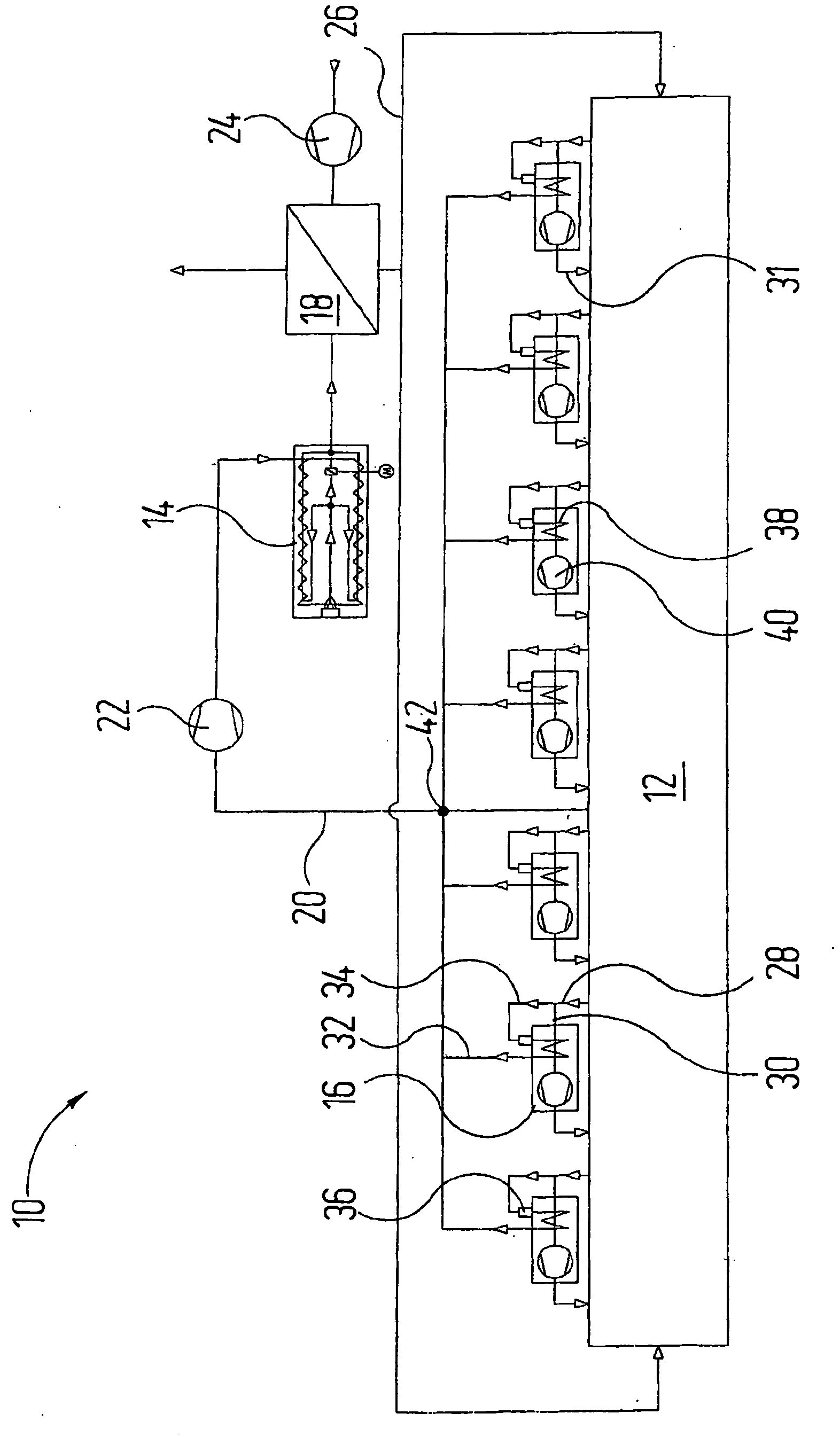
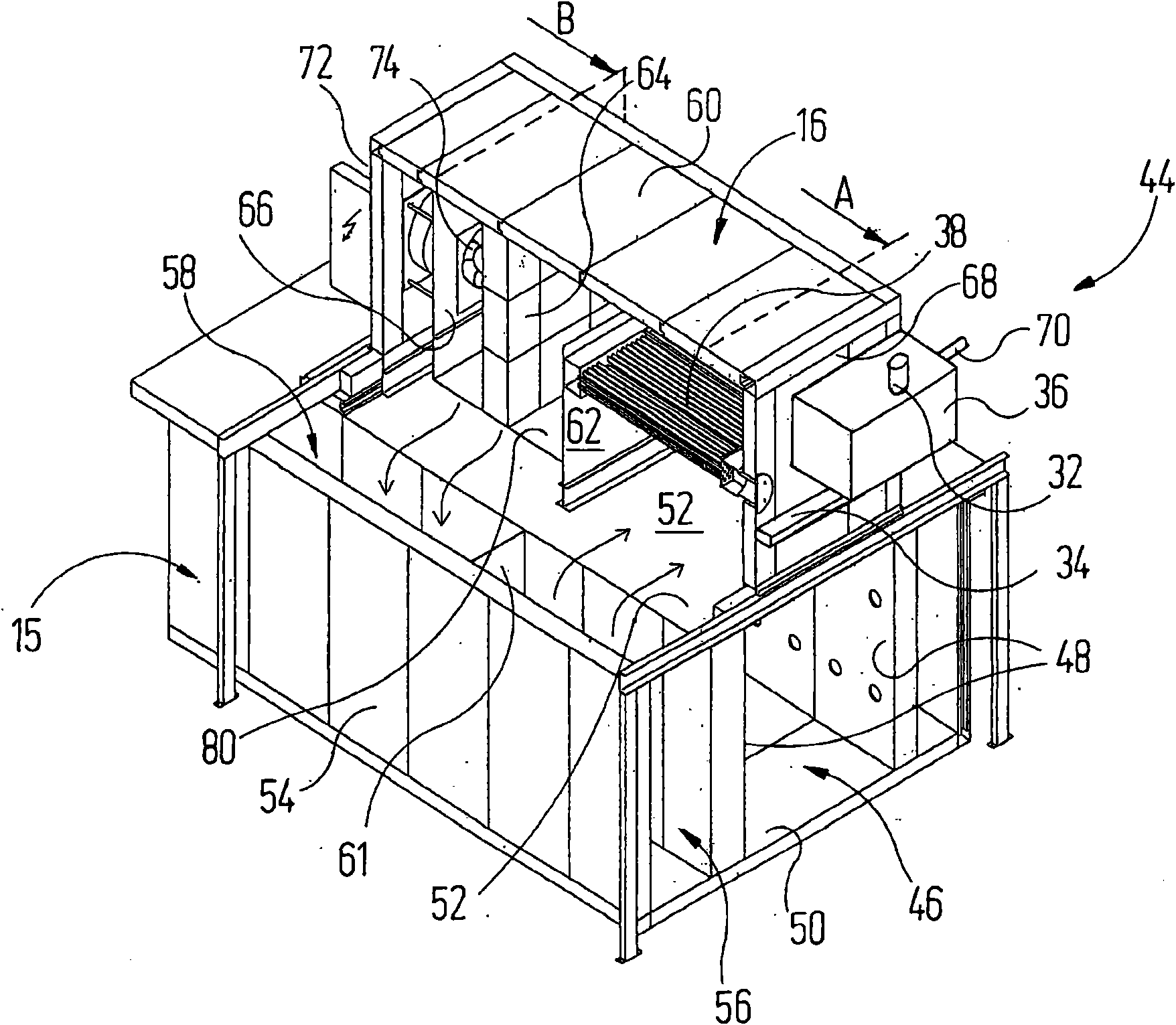
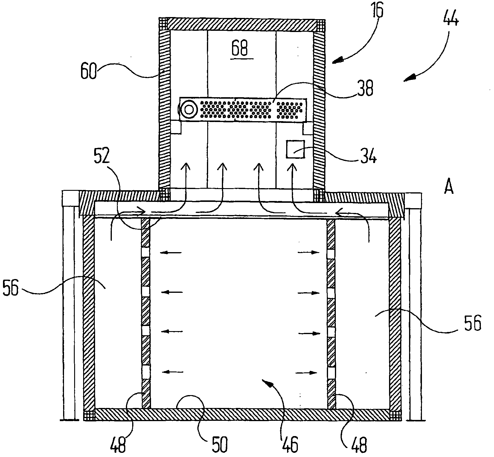
[0031] exist figure 1 The dryer 10 schematically shown in FIG. 2 comprises a dryer housing 12 through which a motor vehicle body (not shown) can pass during continuous operation. Heated air is supplied to the dryer housing 12 in order to start and / or accelerate the drying process of the paint applied to the motor vehicle body and / or to promote crosslinking of the paint. The dryer housing 12 is perpendicular to figure 1 There is a substantially rectangular cross-section in the sectional plane of the drawing plane, as can also be determined by Figures 2 to 4 as seen in the view.

[0032] A thermal post-combustion device 14 , a plurality of heating units 16 and a heat exchanger 18 with the same structure are arranged above the dryer shell 12 .

[0033] The thermal afterburner 14 is a gas burner that mixes exhaust air from the dryer shell 12 supplied via an exhaust air duct 20 and an exhaust air blower 22 for conveying the exhaust air with natural gas and makes the The mixtur...


PUM


Abstract

The invention relates to a dryer for a lacquering facility: a) having a dryer housing (12), in which heated air is circulated, b) having an exhaust air line (20) for a exhausting exhaust air from the dryer housing (12); c) having a combustion unit (14), which is connected to the exhaust air line (20), and which is used for thermal post-treatment of the exhaust air from the dryer housing (12) and for providing hot air to a heat exchanger (18); d) wherein said heat exchanger (18) is set up to supply said dryer housing (12) with heated fresh air; and wherein e) at least one heating unit (16) for heating the air circulated in said dryer housing (12) is associated with said dryer housing (12). It is provided according to the invention that a combustion air supply (34) of the heating unit (16) is connected so it communicates with the dryer housing (12).

Description

technical field [0001] The invention relates to a drier for coating equipment, the drier [0002] a) having a dryer housing in which heated air circulates; [0003] b) have a discharge air duct for discharging the discharge air from the dryer housing; [0004] c) have a burner connected to the exhaust air pipe for thermal aftertreatment of the exhaust air coming out of the dryer housing and for supplying heated air to the heat exchanger; [0005] d) where the heat exchanger is arranged to supply heated fresh air to the dryer shell, and [0006] e) The dryer housing is equipped with at least one heating device for heating the air circulating in the dryer housing. Background technique [0007] A dryer known from the prior art is used for drying paint coats on motor vehicle bodies and for this purpose is supplied with heated air in a dryer housing, also known as a dryer tunnel. Solvents contained in the paint layer can be evaporated by means of the heated air in order to ha...

Claims


Application Information

Patent Timeline
Patent Type & Authority Applications(China)
IPC IPC(8): F26B23/02
CPCF26B23/022F26B2210/12
Inventor P·施维尔P·奥博斯特费尔德
Owner 艾森曼机械设备上海有限公司
Learn More