
Reciprocating rotary frame

A technology of reciprocating rotation and rotating shaft, applied in the direction of conveyor objects, transportation and packaging, etc., can solve the problems of low work efficiency, high labor intensity, difficult handling, etc., achieve simple structure, improve handling speed, save manpower and material resources Effect

Inactive Publication Date: 2011-02-09
牛力机械制造有限公司
View PDF5 Cites 13 Cited by
  • Summary
  • Abstract
  • Description
  • Claims
  • Application Information

AI Technical Summary

Problems solved by technology

[0003] The purpose of the present invention is to provide a reciprocating turret to overcome the above-mentioned shortcomings of difficult product handling, high labor intensity and low work efficiency

Method used


Image

  • Reciprocating rotary frame
  • Reciprocating rotary frame
  • Reciprocating rotary frame

Examples


Embodiment Construction

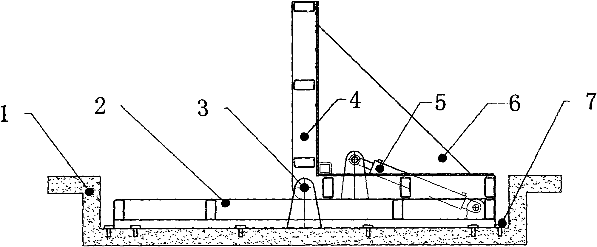
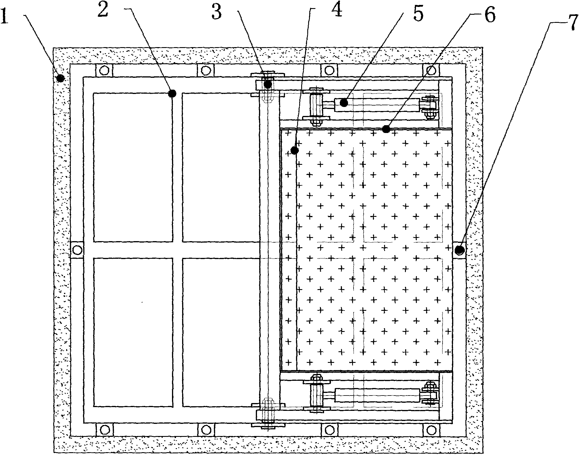
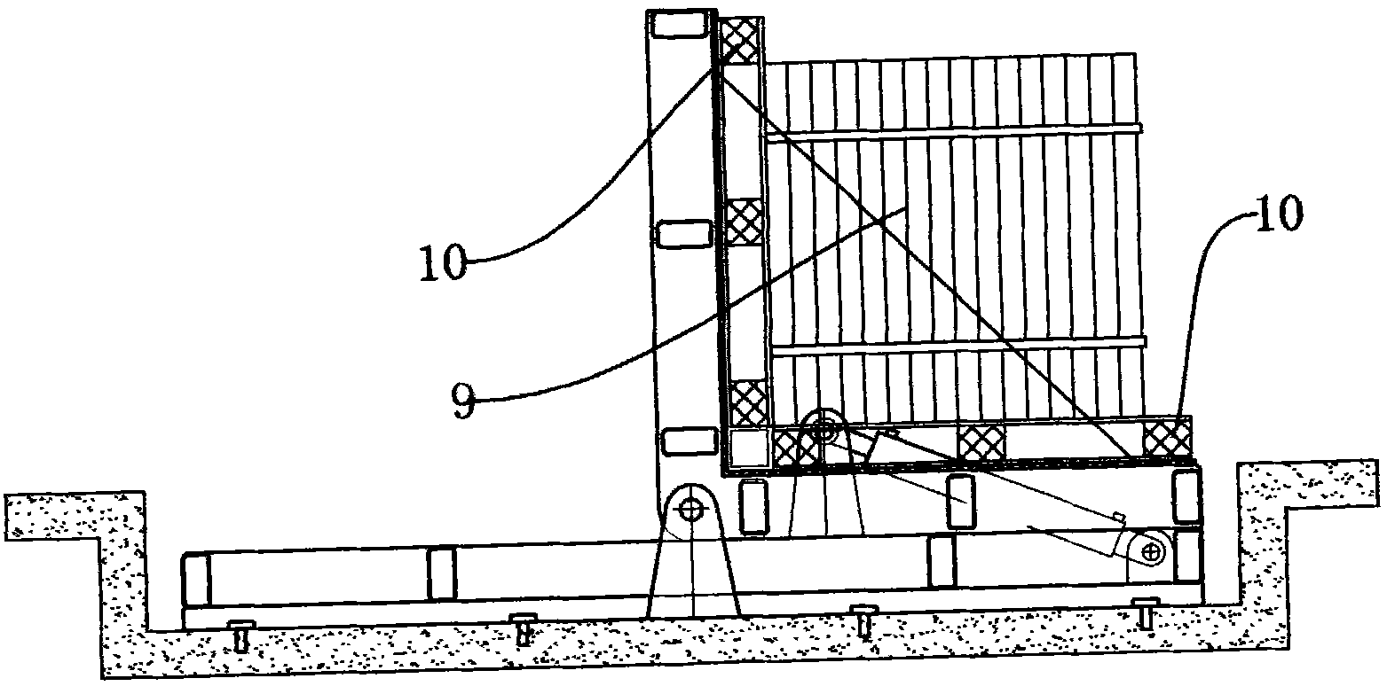
[0019] like Figure 1-2 As shown, the reciprocating turret described in the embodiment of the present invention includes a base 2, a rotary table 4, and a working oil cylinder 5. The base 2 is fixed in the pit 1 by anchor screws 7, and the middle of both sides of the base 2 is provided with Turn the shaft pin assembly 3, the upper side of the base 2 is provided with a rotary table 4, the rotary table 4 is an "L" shaped structure, the bending part of the rotary table 4 is hinged to the rotary shaft pin assembly 3 through a pin shaft Above, the rotary table 4 can rotate the pin shaft assembly 3 to turn over the axis. There is a working oil cylinder 5 between the rotary table 4 and the base 2. The working oil cylinder 5 can push the rotary table 4 to rotate, so that the rotary table 4 Under the action of the working oil cylinder 5, it can rotate 90° back and forth around the rotating pin shaft assembly 3.

[0020] The working oil cylinder 5 is arranged on both sides of the base ...


PUM


Abstract

The invention relates to a reciprocating rotary frame. The reciprocating rotary frame comprises a base, a rotary workbench and an operating cylinder, wherein the rotary workbench is arranged on the upper side of the base, and has an L-shaped structure; and the operating cylinder is arranged between the rotary workbench and the base. The invention has the advantages that: reciprocating rotary frame has a simple structure, is convenient to use and easy to popularize; a hydraulic system is unique, is stable to run and has high safety performance; and the automatic control replaces manual operation, massive manpower and material resources are saved, the cost is reduced, the worker safety is improved, the manual damage probability is reduced, the moving speed is improved and the product quality is guaranteed.

Description

technical field [0001] The invention relates to the field of logistics handling equipment, in particular to a reciprocating turret which is very convenient and suitable for use on the production line of a floor tile production enterprise. Background technique [0002] At present, on the production lines of floor tile manufacturers in the market, most of the floor tiles are carried and turned manually, which is neither safe nor labor-saving, and at the same time, the efficiency is low. In floor tile production enterprises, floor tiles are not only smooth in surface, but also fragile in material. In the process of processing, molding and transportation, the angle must be rotated constantly, sometimes placed horizontally for processing, sometimes placed vertically, and sometimes turned around for packaging and transportation. It is heavy, and workers can only work in the form of dispersing → combining → redispersing → recombining one by one. The actions that can be completed at...

Claims


Application Information

Patent Timeline
Patent Type & Authority Applications(China)
IPC IPC(8): B65G47/248
Inventor 杨远
Owner 牛力机械制造有限公司
Learn More