
Vertical conveying system for core winding frame

A conveying system and coil core technology, applied in the field of conveying technology, can solve the problems of worn coil surface, difficulty and difficulty in quick maintenance, etc., and achieve the effects of reducing equipment failure rate, facilitating normal operation, and easy control.

Active Publication Date: 2011-02-09
青岛雷霆重工股份有限公司
View PDF2 Cites 13 Cited by
  • Summary
  • Abstract
  • Description
  • Claims
  • Application Information

AI Technical Summary

Problems solved by technology

[0004] The above-mentioned double-arm mandrel system is a set of equipment integrating mechanical, electrical, and hydraulic controls. Its structure is complex and its integration is relatively high. In actual use, the failure rate is also relatively high. The relatively high level of integration brings difficulties to rapid maintenance and will cause the entire process to fail to work normally
Also, it is difficult to replace the mandrel, which is constantly in contact with the coil
[0005] In addition, in the above process, after the coil leaves the mandrel of the double-arm mandrel system, it will directly contact the subsequent equipment, which will wear the surface of the coil, thereby greatly affecting the appearance quality of the coil, especially when the rolling mill When making high-quality smooth coils, the use of equipment in the above process cannot stably control the surface quality of the coils
[0006] In addition, the coil temperature after air-cooling treatment is still around 600 degrees Celsius, which requires sufficient cooling sections in the subsequent process. Since the P / F line cooling system can only be arranged along the length direction, it will undoubtedly occupy more workshops space

Method used


Image

  • Vertical conveying system for core winding frame
  • Vertical conveying system for core winding frame
  • Vertical conveying system for core winding frame

Examples


Embodiment Construction

[0055] The specific embodiments provided by the present invention will be described in detail below in conjunction with the accompanying drawings.

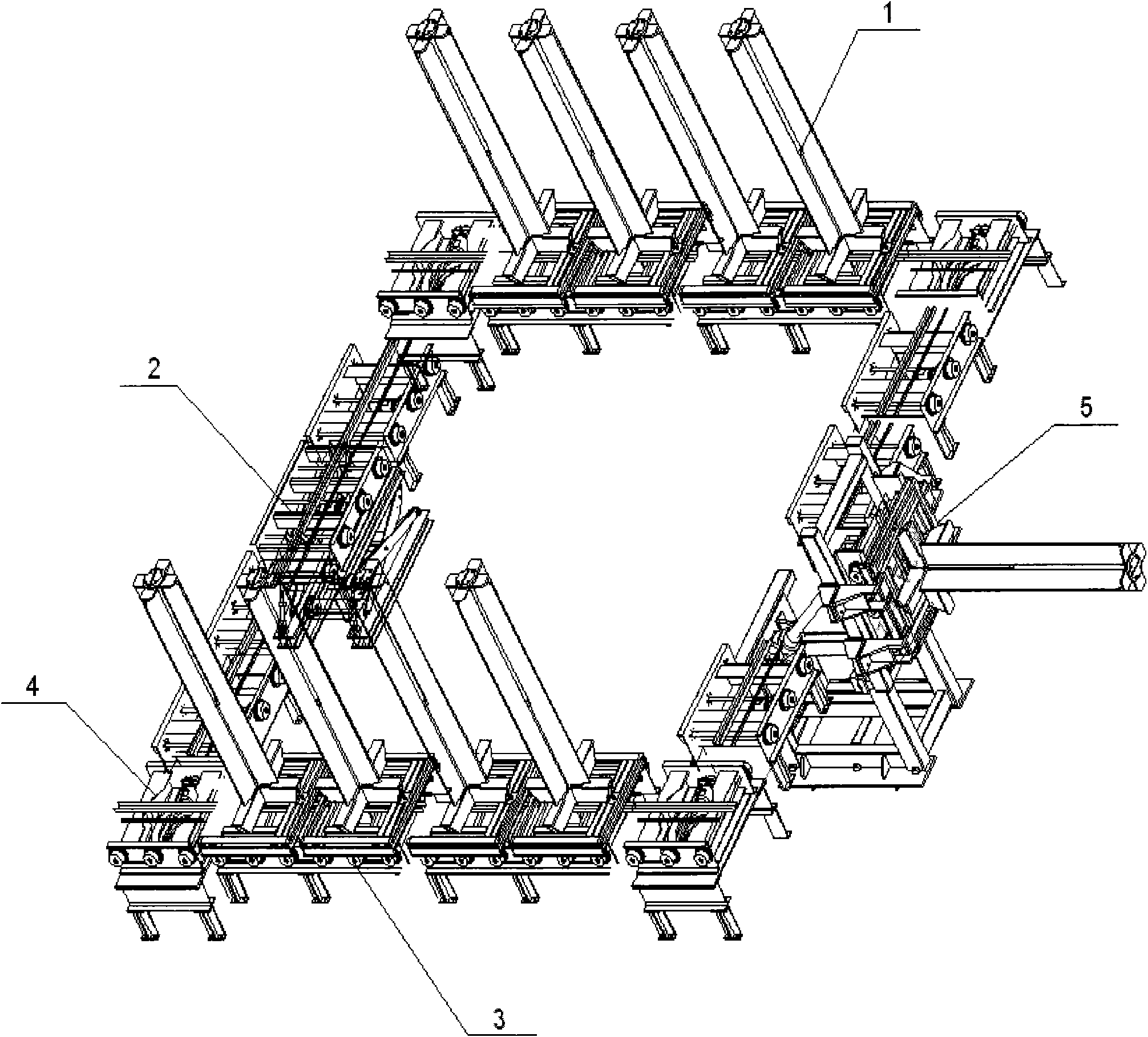
[0056] The first embodiment provided by the present invention is a vertical core frame conveying system, its structure is as follows figure 2 As shown, it includes: core frame 1, lifting roller bed 2, conveying roller bed 3, rotating roller bed 4, and turning roller bed 5.

[0057] The lifting roller bed 2 clamps the core frame 1, and lifts it to the collecting drum to accept the coil, then falls back to release the core frame 1, and conveys it to the conveying roller bed 3; the conveying roller bed 3 carries the loading The core frame 1 with coils, when it needs to turn, transports the core frame 1 to the rotating roller bed 4 to realize the steering of the core frame 1; finally, the rolling core frame 1 is turned over to the level by the turning roller bed 5, and then The coils on the core frame 1 are picked up by the rolling ...


PUM


Abstract

The invention provides a vertical conveying system for a core winding frame, which comprises the core winding frame, a lifting roller machine, a turning roller machine, a conveying roller machine and a rotating roller machine, wherein, the core winding frame bears coils; the lifting roller machine clamps and lifts the core winding frame to a coil collecting drum for bearing the coils and then returns and delivers the core winding frame; the turning roller machine turns over the delivered core winding frame to a horizontal position; the conveying roller machine horizontally conveys the core winding frame; and the rotating roller machine horizontally rotates 90 degrees. In the invention, the coils are born by the equipment with simple structures, thus being easier to control, lowering faultrate of the equipment and being more beneficial to normal operation of the whole process; in addition, the conveying roller machine is arranged between the lifting roller machine and the turning roller machine for conveying the core winding frame carrying the coils, which avoids direct contact between the coil surfaces and the conveying roller machine so as to stably control the surface quality of the coils. In addition, the conveying system of the invention is equipped with the rotating roller machine for changing the delivery direction of the core winding frame, which greatly saves plant space on the premise of guaranteeing sufficient cooling sections.

Description

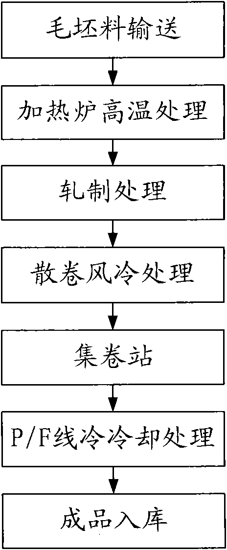
technical field [0001] The invention relates to the fields of iron and steel and metallurgy, in particular to a conveying technology. Background technique [0002] In the wire rod rolling project of the existing steelworks, the commonly used process flow is as follows: figure 1 Shown: [0003] First, rough materials such as iron ore and steel billets are sent to the heating furnace for high temperature treatment and initially form slabs; then these slabs are sequentially subjected to rough rolling, intermediate rolling, pre-finish rolling, and finish rolling to form Formed coils; Next, these formed coils are sent to the loose coil air-cooling system for air-cooling and cooling treatment, so that the temperature is partially reduced. For a 2-ton coil (the specification is usually Φ1250×Φ850L= 3000mm), the temperature after air cooling is about 600 degrees Celsius. These coils are then sent to the coil collection station, where the main equipment in operation is the double-...

Claims


Application Information

Patent Timeline
IPC IPC(8): B65G47/248B65G13/07B65G47/04B65G13/00B65G37/00
Inventor 王进
Owner 青岛雷霆重工股份有限公司
Learn More