


Quick Research
Generate reliable direction feasibility study reports for your R&D in just a few steps.

Technical Q&A
Discover and master advanced knowledge NOW. Basics, ideas, possibilities, all at once.

Find Solutions
As an expert in R&D theories, this can generate solutions to your technical problems instantly.

Evaluate Feasibility
Analyze your overall solution with one click, know your potential R&D risks in advance.

Monitor Landscape
Get weekly tech updates, stay abreast of the latest tech innovations and key insights.
Manual hydraulic gate valve
A hydraulic and gate valve technology, applied in the field of gate valves, can solve problems such as loss of control of pipeline valves and economic losses, and achieve the effect of compact structure
- Summary
- Abstract
- Description
- Claims
- Application Information
AI Technical Summary
Problems solved by technology
Method used
Image

Examples
Embodiment 1
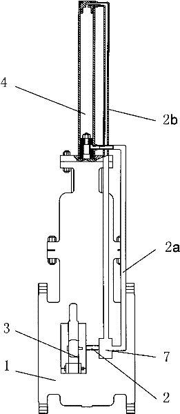
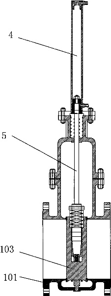
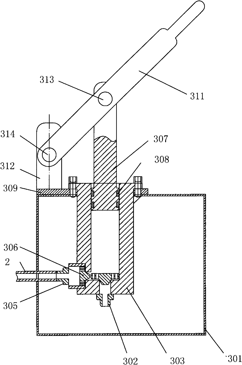
[0016] Such as figure 1 As shown, the manual hydraulic gate valve in the present invention includes a gate valve 1 and a manual hydraulic control device 3 that can drive the gate valve to lift up and down. The gate valve 1 includes: a gate valve body 101 , a gate plate 102 , and a valve stem 5 . Such as figure 2 As shown, the manual hydraulic control device includes a hydraulic cylinder 4 , an oil pipe 2 , a reversing valve 7 and a hydraulic device 3 . The hydraulic cylinder 4 is connected with the hydraulic device 3 through the oil pipe 2 .
[0017] Such as figure 1 , 2 As shown, the hydraulic cylinder 4 in the manual hydraulic control device is set 3 on the upper end of the gate valve body 101, and the upper end of the valve stem 5 is fixedly connected with the piston 403 in the hydraulic cylinder 4 of the manual hydraulic control device. Two oil inlet holes 401 and 402 are respectively provided at both ends of the hydraulic cylinder 4 . One end of the oil pipe 2 is c...
PUM
 Abstract
Description
Claims
Application Information
 - R&D Engineer
- R&D Manager
- IP Professional
- Industry Leading Data Capabilities
- Powerful AI technology
- Patent DNA Extraction
Browse by: Latest US Patents, China's latest patents, Technical Efficacy Thesaurus, Application Domain, Technology Topic, Popular Technical Reports.
© 2024 PatSnap. All rights reserved.Legal|Privacy policy|Modern Slavery Act Transparency Statement|Sitemap|About US| Contact US: help@patsnap.com