chain tensioner

A chain tensioner and tensioner technology, applied in the direction of transmission, belt/chain/gear, mechanical equipment, etc., can solve the problems of increased manufacturing cost, complex structure, difficult to make an assembleable or disassembled shape, etc. , to achieve the effect of reducing manufacturing cost and simple structure

Active Publication Date: 2016-04-27
TSUBAKIMOTO CHAIN CO
View PDF6 Cites 1 Cited by
  • Summary
  • Abstract
  • Description
  • Claims
  • Application Information

AI Technical Summary

Problems solved by technology

[0005] However, the ratchet mechanism of this known chain tensioner also limits the movement of the plunger to the accommodation direction caused by the excessive chain tension caused by the temperature change of the engine, etc., and there is sintering of the plunger, or the chain continues The problem of increased burden on the chain and noise caused by running under excessive tension
[0006] Therefore, although a predetermined amount of backlash is set for the ratchet mechanism so as to match the maximum value of the plunger moving in the receiving direction due to excessive chain tension, there is a problem that the greater the amount of backlash, the lower the start-up. The problem that the worse the effect of the slap sound
[0007] In addition, when the engaging member provided on the main body of the tensioner is constituted by a cam mechanism having a protruding portion outside the main body of the tensioner, the structure is complicated and the outer shape of the main body of the tensioner is enlarged. Into an assembleable or disassembled shape
[0008] Furthermore, it is necessary to design a ratchet mechanism with different characteristics according to various usage conditions, but the whole tensioner must be designed according to the characteristics corresponding to the usage conditions, so there is a problem of increasing the manufacturing cost.

Method used


Image

  • chain tensioner
  • chain tensioner
  • chain tensioner

Examples


Embodiment 1

[0039] Hereinafter, a chain tensioner which is an embodiment of the present invention will be described based on the drawings.

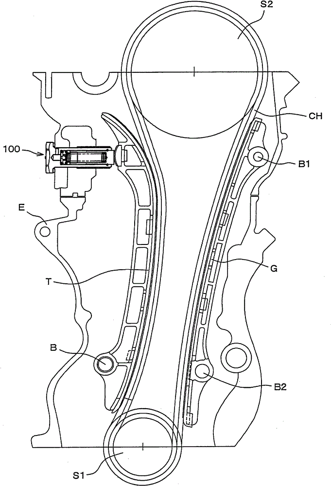
[0040] The chain tensioner 100 of the present invention is, for example, a timing system for an engine.

[0041] Such as figure 1 As shown, the timing system of the engine is to use the transmission chain CH, press contact with the tension rod T which properly maintains the tension of the transmission chain CH and guides the transmission chain CH, and the fixed guide part G which guides the operation of the transmission chain CH, wherein the transmission The chain CH is endlessly suspended between the driving sprocket S1 mounted on the crankshaft in the engine room formed by the engine block E and the driven sprocket S2 mounted on the camshaft.

[0042] The tension rod T is freely swingably installed in the engine room through the installation shaft B, and is pressed and applied by the chain tensioner 100 inserted and fixed on the engine block E fr...

Embodiment 2

[0067] Next, based on Figure 9 Another embodiment of the elastic ring is described.

[0068] In this embodiment, the elastic ring is composed of an annular ring 230, which is formed of an elastic material with a circular cross-section whose diameter can be reduced and expanded, and the rods 231, 232 are extended on the outer peripheral side. The tightening device main body 210 is provided with a notch communicating from a part of the outer periphery of the annular groove to the outside.

[0069] The outer peripheral diameter and inner peripheral diameter of the annular portion of the annular ring 230 are formed in the same manner as the above-mentioned C-shaped ring 130 .

[0070] In addition, one rod portion 231 is extended to the outside through the notch, and the other rod portion 232 is formed in an L-shape so that movement of the annular ring 230 in the circumferential direction is restricted within the notch.

[0071] Thereby, diameter expansion and contraction can be...

Embodiment 3

[0074] based on Figure 10 Still another embodiment of the elastic ring will be described.

[0075] In this embodiment, the elastic ring is composed of an annular ring 330. The annular ring 330 is formed of an elastic material with a circular cross-section whose diameter can be reduced and expanded, and the rods 331, 332 are extended on the outer peripheral side. The tightening device main body 310 is provided with a notch communicating from a part of the outer periphery of the annular groove to the outside.

[0076] The outer peripheral diameter and inner peripheral diameter of the annular portion of the annular ring 330 are formed in the same manner as the above-mentioned C-shaped ring 130 .

[0077] In addition, the rods 331, 332 on both sides are bent in the shape of a crankshaft in the notch, and the front ends thereof extend to the outside of the main body 310 of the tensioner. Movement of the annular ring 330 in the circumferential direction is restricted.

[0078] T...


PUM


Abstract

The present invention provides a chain tensioner, which can reduce manufacturing cost with a simple structure, does not restrict the movement of the plunger to the accommodation direction due to excessive chain tension, prevents the sintering of the plunger, and reduces the burden on the chain and Noise, and reduce the amount of backlash, reduce the beating sound when starting, and can be miniaturized, easy to assemble, disassemble and maintain. In the chain tensioning of the ratchet mechanism constituted by a plurality of concave and convex grooves (121) arranged on the outer periphery of the plunger (120) and a C-ring (130) accommodated in the annular groove (115) of the tensioner main body (110) In the device (100), the two side walls of the annular groove (115) are formed as inclined surfaces with different angles.

Description

technical field [0001] The present invention relates to a chain tensioner in which a plunger is freely slidably inserted into a tensioner main body having a cylindrical plunger receiving hole open at one end, and is urged in a protruding direction to properly hold a chain tension. Background technique [0002] As is well known, conventionally, in a chain guide mechanism that slides and guides a transmission chain such as a roller chain by using a running guide shoe, in order to properly maintain the tension, a chain tensioner having a plunger is used to apply force to a tension rod having a running guide shoe. , the above-mentioned roller chain ring is suspended and looped between the sprockets on the crankshaft and the camshaft respectively arranged in the engine room, and the above-mentioned plunger can protrude from the fixed tensioner main body to the protruding direction under the action of loading force. [0003] In the above-mentioned chain tensioner, it is well know...

Claims


Application Information

Patent Timeline
Patent Type & Authority Patents(China)
IPC IPC(8): F16H7/08
CPCF16H7/0836F16H7/0848F16H2007/0812F16H2007/0853F16H2007/0855F16H2007/0859F16H2007/0891F16H2007/0851
Inventor 榑松勇二早见淳志
Owner TSUBAKIMOTO CHAIN CO
Why Eureka
Try Eureka