Masonry structure and method for enhancing collapse resistance and integrity under strong earthquake

A kind of masonry structure and integral technology, applied in the direction of building components, building structure, building material processing, etc., can solve the problems of limited ability to resist horizontal loads, low rigidity of weak frame structures, and small effect of geometric shapes, etc., to achieve The effect of enhancing the ability to resist horizontal loads, maintaining geometric invariance, and improving the ability to resist horizontal loads

Inactive Publication Date: 2011-11-30
ZHEJIANG UNIV
View PDF4 Cites 0 Cited by
  • Summary
  • Abstract
  • Description
  • Claims
  • Application Information

AI Technical Summary

Problems solved by technology

[0004] However, although the structural columns and ring beams around the wall form certain deformation constraints, due to the low rigidity of the weak frame structure formed by the structural columns and ring beams, the ability to resist horizontal loads is very limited. Its nodes are easy to produce plastic hinges to form a mechanism, that is, a geometrically variable body, and the wall will collapse and fail immediately.
Under the earthquake, the collapse of the restraint wall often manifests in two forms. One is the collapse of the force in the plane. At this time, the crack is first caused by the insufficient strength of the wall material, and the crack develops so that the wall partially withdraws from work. After the body cracks, the structural columns and ring beams constraining the wall bear relatively greater internal force, until the weak frame is damaged, the wall becomes a geometrically variable body, and the wall collapses; the second form is the out-of-plane Stress, the current structural structure only transmits the load to the vertical walls on both sides through the tie bars with the structural columns, which has little effect on maintaining the geometric shape of the wall. Stable, very low collapse resistance

Method used


Image

  • Masonry structure and method for enhancing collapse resistance and integrity under strong earthquake
  • Masonry structure and method for enhancing collapse resistance and integrity under strong earthquake
  • Masonry structure and method for enhancing collapse resistance and integrity under strong earthquake

Examples


Embodiment Construction

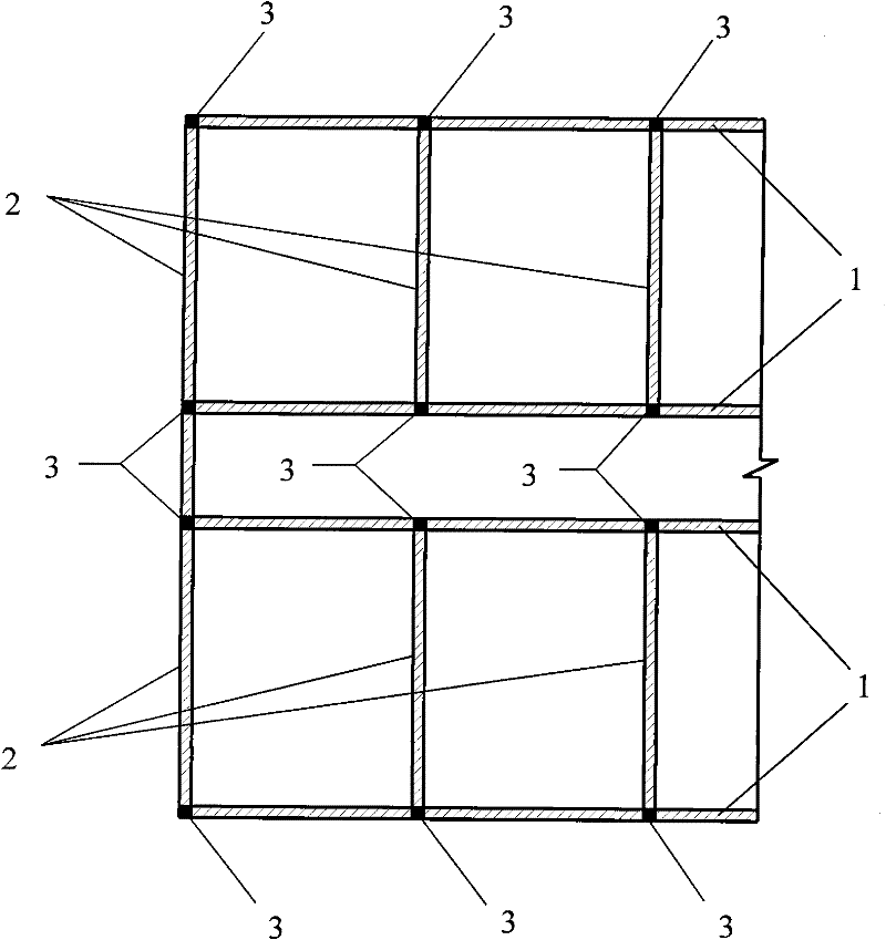
[0036] figure 1 It is a local layout plan of the existing masonry structure. Structural columns 3 are arranged at the junction of the longitudinal wall 1 and the transverse wall 2, and are connected up and down. Since the lengths of the longitudinal wall 1 and the transverse wall 2 are different, and different seismic fortification intensities of structures require different intervals of the structural columns 3 , the spacing of the structural columns 3 is not fixed. Such as figure 1 As shown, the spacing of the structural columns 3 arranged in the longitudinal wall 1 is the same as the story height, and the spacing of the structural columns 3 arranged in the transverse wall 2 is larger than the story height.

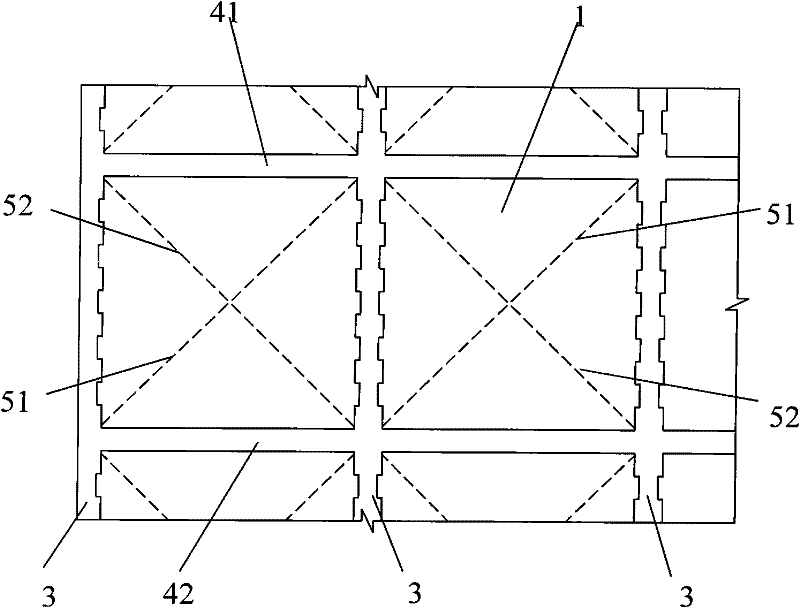
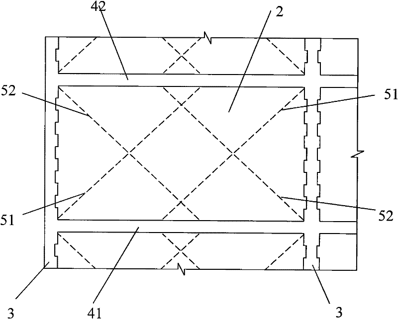
[0037] figure 2 It is a schematic diagram of the elevation of the structure after setting a group of reinforcing steel bars between two adjacent structural columns according to the present invention. A ring beam 4 is arranged at the joint between the floor and the ...


PUM


Abstract

The invention discloses a masonry structure and a method for enhancing collapse resistance and integrity under a strong earthquake. In a wall between an upper ring beam and a lower ring beam which are close to each other, more than one group of bored bricks is laid between two adjacent constructional columns, wherein each group of bored bricks comprises a first row of bored bricks and a second row of bored bricks, bore channel center lines of all the bored bricks on the first row (i.e. first bore channel center lines) coincide, bore channel center lines of all the bored bricks on the second row (i.e. second bore channel center lines) coincide, and the first bore channel center lines and the second bore channel center lines are distributed in a tilted way and intersect with each other; reinforced steel bars are respectively penetrated through the bore channels of the bored bricks in the first row and the second row, the lower end of each reinforced steel bar is fixedly connected with aU-shaped embedded part, the U-shaped embedded part is embedded in the lower ring beam, and the upper end of each reinforced steel bar is anchored in the upper ring beam or the steel bar of the corresponding constructional column.

Description

technical field [0001] The invention relates to a masonry structure and method for enhancing collapse resistance and integrity under strong earthquakes, which can be applied to masonry structures such as ordinary brick masonry and concrete blocks, and can effectively enhance the masonry structure under strong earthquakes. Anti-collapse ability, improve the integrity of masonry structure. Background technique [0002] Masonry structure is currently one of the main structural types of house construction in my country. Generally used as residential, office, school, hospital and other civil and public buildings, it will still have a very wide application value for a long time to come. Due to the material and the way a masonry structure is constructed, its ability to resist horizontal loads is much lower than its ability to resist vertical loads. Under earthquake action, horizontal cracks and cross cracks occur in the masonry wall, and the wall is damaged with out-of-plane disl...

Claims


Application Information

Patent Timeline
Patent Type & Authority Patents(China)
IPC IPC(8): E04H9/02E04B2/64E04B2/02E04B2/14E04C1/39E04G21/00E04G21/12
Inventor 肖南李莎华晨赵文争
Owner ZHEJIANG UNIV
Why Eureka
Try Eureka