Eureka AIR delivers breakthrough ideas for toughest innovation challenges, trusted by R&D personnel around the world.

Dual-Sepic buck-boost output parallel combined inverter

A buck-boost and combined technology, which is applied in the direction of output power conversion device, conversion of AC power input to DC power output, photovoltaic power generation, etc., can solve the problems of increasing system cost conversion efficiency and avoid bridge arm through problems, Suppress power fluctuations and achieve simple effects

Inactive Publication Date: 2011-01-26
YANSHAN UNIV
View PDF1 Cites 18 Cited by
  • Summary
  • Abstract
  • Description
  • Claims
  • Application Information

AI Technical Summary

Problems solved by technology

Another solution is to process a frequency step-up transformer after the inverter to increase the AC voltage on the output side. Obviously, the addition of a transformer will increase the system cost and affect the overall conversion efficiency.

Method used


Image

  • Dual-Sepic buck-boost output parallel combined inverter
  • Dual-Sepic buck-boost output parallel combined inverter
  • Dual-Sepic buck-boost output parallel combined inverter

Examples


Embodiment Construction

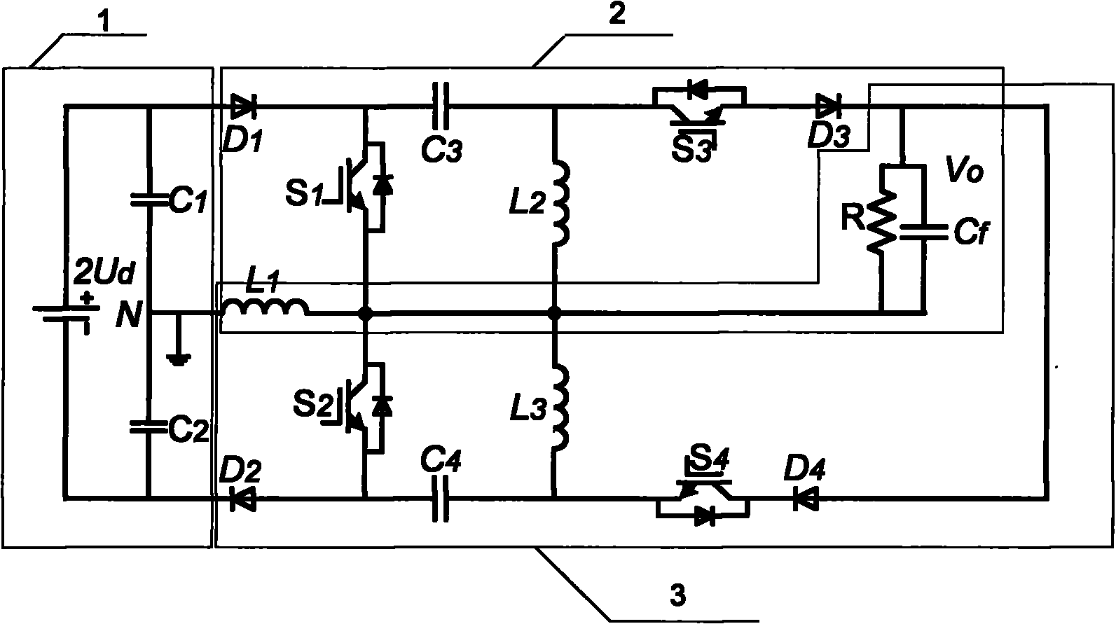
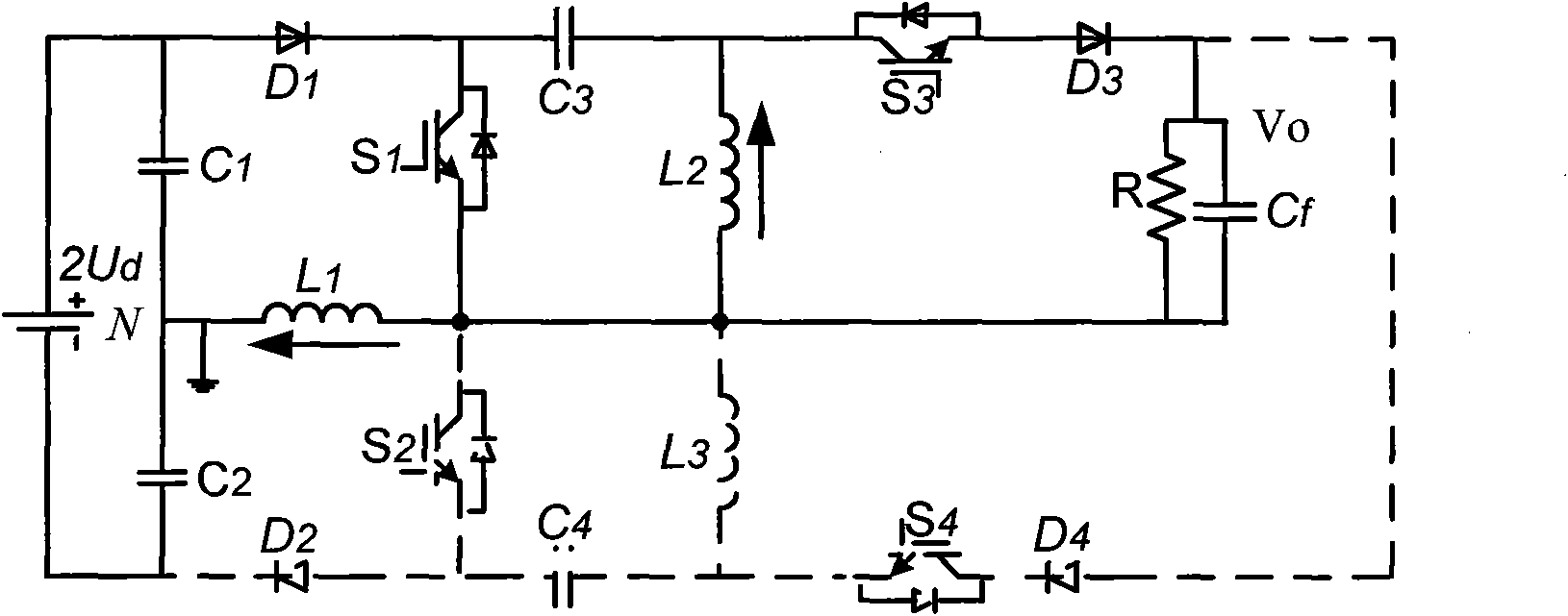
[0021] as attached figure 1 As shown, the double Sepic buck-boost output parallel combined inverter of this embodiment includes a capacitor voltage divider circuit 1, a first Sepic circuit 2 and a second Sepic circuit 3; the capacitor voltage divider circuit consists of two serially connected first Sepic circuits A capacitor C1 and a second capacitor C2 are formed, the series connection point of the first capacitor and the second capacitor is connected to the zero potential point N, the other end of the first capacitor is connected to the positive pole of the external power supply 2Ud, and the other end of the second capacitor is connected to the negative pole of the external power supply 2Ud ; In the first Sepic circuit, the anode of the first power diode D1 is connected to the positive pole of the power supply 2Ud, the cathode is connected to the anode of the first power switch tube S1 and one end of the third capacitor C3, and the cathode of the first power switch tube is co...


PUM


Abstract

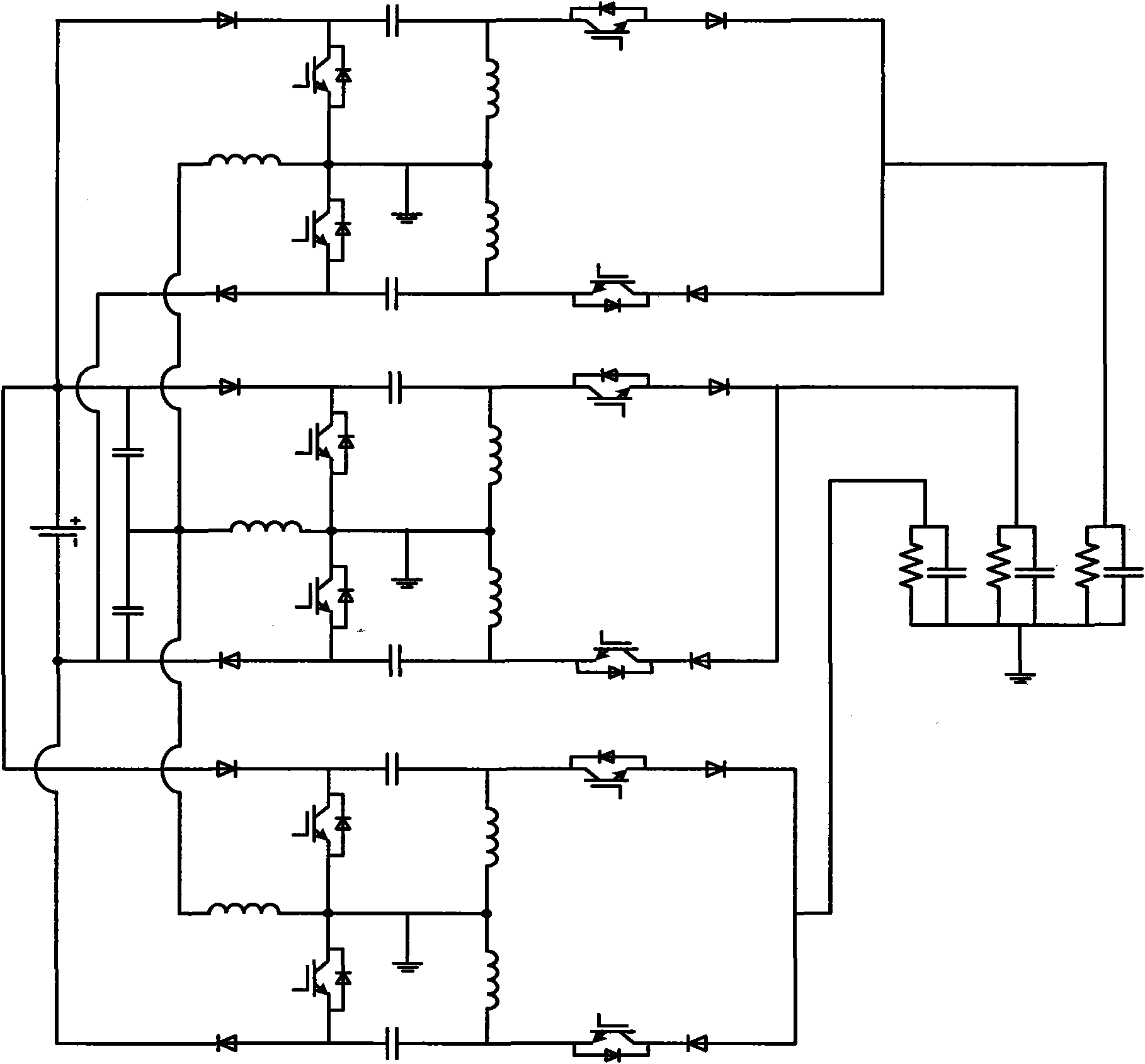
The invention discloses a dual-Sepic buck-boost output parallel combined inverter, which comprises two buck-boost Speic DC / DC circuits that are connected in parallel at the output side, and which can realize the buck-boost single-phase inversion and expand the buck-boost single-phase inversion in a three-phase system to realize the three-phase inversion output. The inverter has the basic function of realizing buck-boost inversion; when the direct-current voltage at the input side is lower or the change range is larger, the dual-Sepic buck-boost output parallel combined inverter still can realize the inversion function; two high-frequency switching tubes adopt a non-complementary work manner and do not work simultaneously, therefore, the bridge through problem is prevented; the circuit parameter designing principle can be designed according to the mature direct-current Sepic converter designing principle; the inductive current works under the continuous state and reduces the influence of the EMI (Electro-Magnetic interference). The invention is mainly applied to the field of renewable energy source or new energy source generation with lower direct-current voltage, faster change or larger fluctuation range, such as photovoltaic power generation, a small Wind turbine generator system, fuel cell generation, and the like.

Description

technical field [0001] The invention is an inverter in an electric energy conversion device, especially in single-phase or multi-phase inverter applications that can boost or lower voltage. Background technique [0002] With the increasing depletion of traditional energy and the destruction of the ecological environment, it is becoming increasingly important to seek environmentally friendly renewable energy and new energy. Solar energy, wind energy, and biomass power generation technologies are the core technologies to cope with the energy crisis and achieve sustainable development. Inverters are an integral part of this type of power generation technology. Compared with traditional thermal and hydroelectric power generation technologies, the installed capacity of renewable energy power generation devices is small, and the output power fluctuates with the fluctuation of natural conditions, showing randomness. The specific performance is the variation range of the DC voltage...

Claims


Application Information

Patent Timeline
IPC IPC(8): H02M7/537H02M1/14
CPCY02E10/56
Inventor 王立乔王欣邬伟扬仇雷
Owner YANSHAN UNIV
Why Eureka
Eureka Blog
Learn More