Self-driven joint
A self-driven, joint technology, applied in the direction of electric components, synchronous motors with stationary armatures and rotating magnets, supporting machines, etc., can solve the problem of a large number of joints, and achieve simple joint structure, high structural strength, and driving efficiency high effect
- Summary
- Abstract
- Description
- Claims
- Application Information
AI Technical Summary
Problems solved by technology
Method used
Image
Examples
Embodiment 1
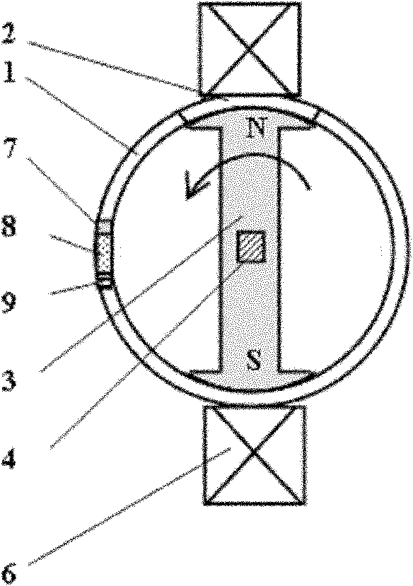
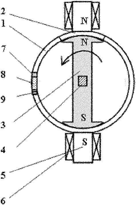
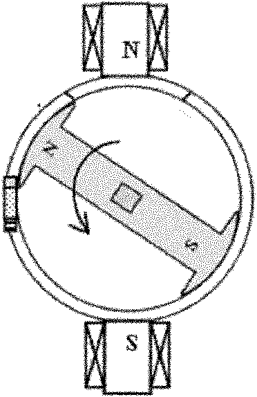
[0029] Such as figure 1 As shown, the intelligent self-driven joint of the present invention includes: a sleeve 1, a magnetic induction device composed of a structural permanent magnet 3 and a rotating output rod 4 fixedly connected thereto, and an electromagnetic coil 6, a fastener 7, a magnetostrictive material The body 8 is tightly pressed on the magnetic field generating device composed of the piezoelectric or compressive strain material connecting body 9, wherein: the magnetic induction device is installed inside the casing 1 while rotating along the axis of the casing 1, and the magnetic field generating device is fixedly arranged outside the casing 1. A pair of electromagnetic coils 6 with opposite polarities are relatively arranged on the outer wall of the sleeve 1, and the magnetostrictive piezoelectric transducer composed of a fastener 7 and a magnetostrictive material body 8 tightly pressed on a piezoelectric or compressively strained material body 9 The sensing dev...
Embodiment 2
[0040] In this embodiment, on the basis of Embodiment 1, a second pair of electromagnetic coils 11 and a second yoke 10 are added, wherein: the second pair of electromagnetic coils 11 with opposite polarities and the first pair of electromagnetic coils 6 with opposite polarities are arranged alternately The outer wall of casing 1.
[0041] Embodiment 2 works by at first counteracting the permanent magnetic attraction force of the initial structural permanent magnet 3 acting on the magnetic material body 2 in the casing 1 by first energizing the electromagnetic coil on the first yoke 5, and then by applying power to the second yoke 10 The electromagnetic coil 11 is supplied with a reverse current, and under the combined action of the electromagnetic repulsion force of the magnetic first yoke iron 5 and the electromagnetic attraction force of the second yoke iron 10, the structural permanent magnet 3 deflects corresponding to the placement angle of the second yoke iron 10, And d...
Embodiment 3
[0044] Such as Figure 6 As shown, the present embodiment adopts the first yoke 5 whose section is an L-shaped structure;
[0045] When this embodiment is working, all its constituent elements and driving action mode are the same as Embodiment 1, but for this working mode, the normal line of the two ends of the first yoke 5 is at an angle of 90 degrees; in the initial position, the first yoke 5 One end surface normal of 5 is coincident ( / perpendicular) or vertical ( / coincident) with the axis of the structural permanent magnet 3 lengthwise direction, such as Figure 6 location shown. Combined with the driving process of working mode 1, in this working mode, the structural permanent magnet 3 can realize the reciprocating rotation driving action of 90 degrees of rotation.
PUM
 Abstract
Description
Claims
Application Information
 - R&D
- Intellectual Property
- Life Sciences
- Materials
- Tech Scout
- Unparalleled Data Quality
- Higher Quality Content
- 60% Fewer Hallucinations
Browse by: Latest US Patents, China's latest patents, Technical Efficacy Thesaurus, Application Domain, Technology Topic, Popular Technical Reports.
© 2025 PatSnap. All rights reserved.Legal|Privacy policy|Modern Slavery Act Transparency Statement|Sitemap|About US| Contact US: help@patsnap.com


