Carbon dioxide-absorbing device for anaesthesia machine

A carbon dioxide and absorption device technology, applied in respirator and other directions, can solve problems such as difficult detection, difficult to detect, and inability to accurately determine the installation position of the isolation diaphragm, so as to achieve uniform axial force and prevent installation from being in place.

Inactive Publication Date: 2011-01-26
深圳市百格医疗技术有限公司
View PDF0 Cites 4 Cited by
  • Summary
  • Abstract
  • Description
  • Claims
  • Application Information

AI Technical Summary

Problems solved by technology

[0003] Existing CO 2 The structure of the absorption device is relatively complex, including CO 2 The absorption tank, and a group of isolation diaphragms connected in parallel between the breathing circuit and the bypass device, are driven by a guide linkage rod to move upward or downward along the axial direction of the guide linkage rod. 2 When the absorption tank is installed in place, the guide linkage rod moves upward, and the isolation diaphragms connected in parallel move upward along the axial direction of the guide linkage rod, CO 2 The absorption device is in communication with the breathing circuit and isolated from the bypass device, forming a CO 2 Absorbed respiration circulatory system; unloads CO 2 After the absorption tank, the guide linkage rod moves downward, and the isolation diaphragm connected in parallel moves down along the axial direction of the guide linkage rod and is isolated from the outside world. 2 The absorption device is in communication with the bypass device and isolated from the breathing circuit, forming no CO 2 Absorbed breathing cycle bypass to replace soda lime or barium hydroxide lime in the absorbing vessel
However, in order to ensure that the entire set of isolation diaphragms have consistent displacement along the axial direction of the guide linkage rod, each isolation diaphragm must have consistent good orientation and stress stability. The processing accuracy and assembly requirements of the isolation diaphragms It is very harsh, and after the isolation diaphragms are connected in parallel, it is difficult to detect, and a slight clamping phenomenon occurs during use, which is not easy to detect, so that it is impossible to accurately judge whether the entire set of isolation diaphragms are installed in place
If it is not installed in place, it will definitely cause CO 2 Relapse, although the anesthesia machine monitoring system can detect CO 2 The concentration is too high and an alarm is issued, however, the patient has inhaled a small amount of CO 2 , will suffer some damage

Method used


Image

  • Carbon dioxide-absorbing device for anaesthesia machine
  • Carbon dioxide-absorbing device for anaesthesia machine
  • Carbon dioxide-absorbing device for anaesthesia machine

Examples


Embodiment Construction

[0019] The present invention will be described below in combination with specific embodiments and with reference to the accompanying drawings.

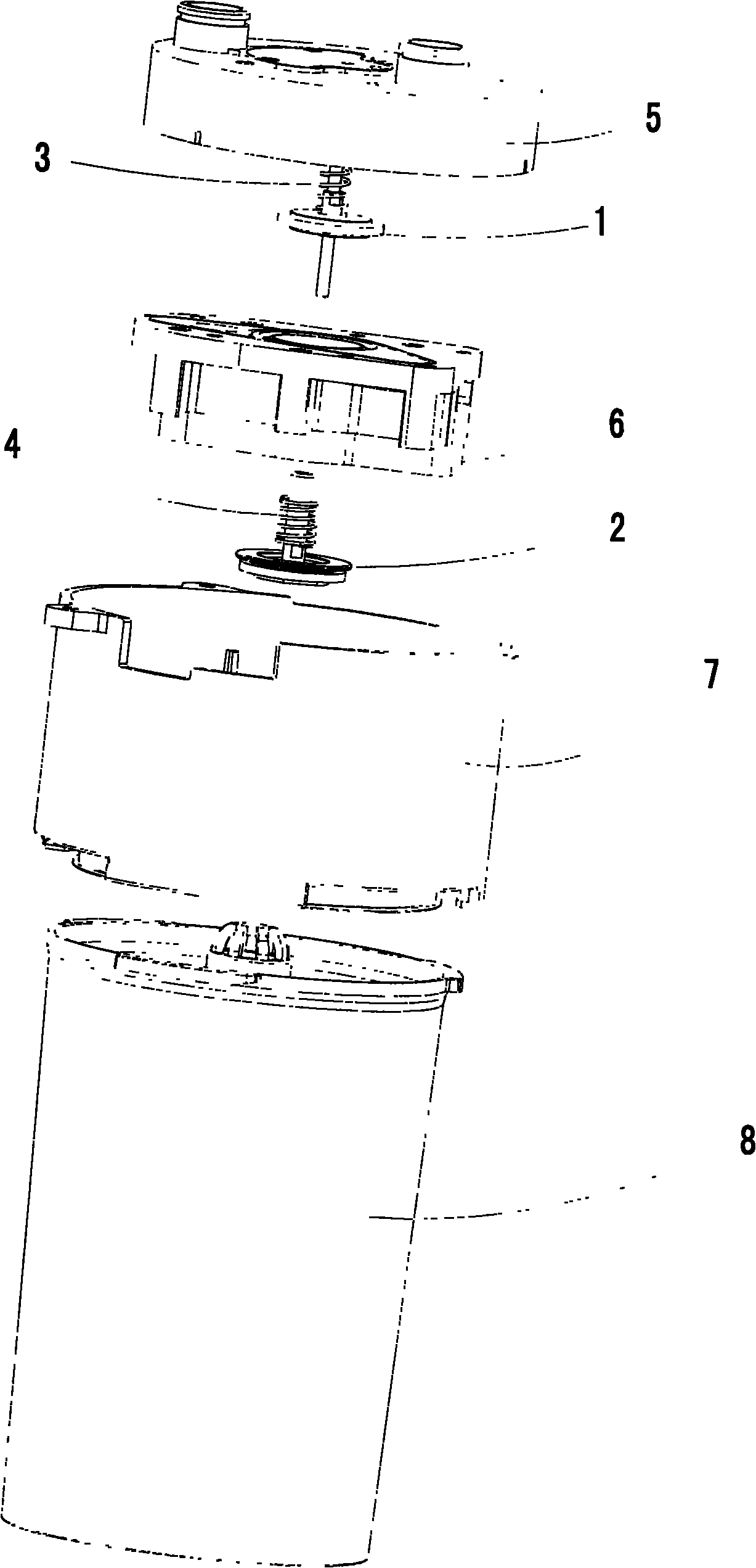
[0020] a kind of like Figure 1~4 Anesthesia machine shown with carbon dioxide absorber, including CO 2 The absorption tank 8, and the control components arranged between the breathing circuit 201 and the bypass device 202.

[0021] The control part is a pilot isolation valve 1 and a transmission isolation valve 2 arranged in series on the installation base 6, and the control part includes a 2 The top block at the top of the absorption tank 8 is linked with the guide linkage rod, the installation base 6 is firmly connected with the bottom of the gas exchange main body 7, the top of the gas exchange main body 7 is tightly connected with the docking seat 5 of the breathing circuit, the guide isolation valve 1 and the transmission isolation valve 2. In the cavity of the gas exchange main body 7, the upward or downward linkage displacem...


PUM


Abstract

The invention discloses a carbon dioxide-absorbing device for an anaesthesia machine. The device comprises a CO2-absorbing tank and a control part which is arranged between a breathing circuit and a bypass device, wherein the control part comprises a guide linkage rod in linkage with a top block arranged at the top end of the CO2-absorbing tank. The device is characterized by a guide isolating valve and a transmission isolating valve which are arranged on a mounting base and are serially connected, wherein the mounting base is tightly connected with the bottom of a gas exchanging main body; the top of the gas exchanging main body is tightly connected with a breathing circuit butt joint seat; and the guide isolating valve and the transmission isolating valve are controlled by the guide linkage rod in a chamber of the gas exchanging main body to move upwards and downwards in a linkage way along the axial direction of the guide linkage rod. The guide isolating valve and the transmission isolating valve of the device are uniformly stressed in the axial direction without position locking phenomenon; the upward displacement distance of the guide isolating valve and the transmission isolating valve can be easily guaranteed; improper CO2-absorbing tank mounting position caused by position locking or an isolating valve upward moving process can be effectively prevented; and risk of hurting patient due to CO2 re-absorption can be avoided.

Description

technical field [0001] The invention relates to a device specially used for anesthesia which affects the patient's respiratory system by means of gas treatment, in particular to a carbon dioxide absorption device for an anesthesia machine. Background technique [0002] The breathing circuit is a combined gas circuit device connected between the anesthesia machine and the patient, which delivers anesthesia mixed gas to the patient and returns the patient's exhaled gas, so as to achieve normal O 2 with CO 2 exchange. CO containing soda lime (a mixture of sodium, potassium, and calcium hydroxide) or barium hydroxide lime (a mixture of barium hydroxide, octahydrohydrate, and calcium hydroxide) 2 Absorber tanks for absorbing CO 2 and moisture to prevent patients from developing CO, which is almost indistinguishable from hypoxia 2 Relapse problem. [0003] Existing CO 2 The structure of the absorption device is relatively complex, including CO 2 The absorption tank, and a g...

Claims


Application Information

Patent Timeline
Patent Type & Authority Applications(China)
IPC IPC(8): A61M16/22A61M16/01A61M16/20
Inventor 郭勇徐波
Owner 深圳市百格医疗技术有限公司
Why Eureka
Try Eureka