Single-phase and three-phase dual-buck type half-bridge parallel active power filter

A power filter, double step-down technology, applied in active power filter, harmonic reduction device, AC network to reduce harmonic/ripple and other directions, can solve the problem of affecting the filtering characteristics of active power filter and affecting system stability It can reduce the switching loss, improve reliability, and control simple effects

Inactive Publication Date: 2011-01-19
NANJING UNIV OF AERONAUTICS & ASTRONAUTICS
View PDF2 Cites 12 Cited by
  • Summary
  • Abstract
  • Description
  • Claims
  • Application Information

AI Technical Summary

Problems solved by technology

So far, parallel-connected active power filters have developed a variety of topologies. The basic unit mainly adopts a half-bridge or full-bridge structure with two switching tubes in series. The stability and reliability of the system, while increasing the dead zone of the switch will also affect the filtering characteristics of the active power filter, which is difficult to be widely used in power grid systems with high reliability requirements

Method used


Image

  • Single-phase and three-phase dual-buck type half-bridge parallel active power filter
  • Single-phase and three-phase dual-buck type half-bridge parallel active power filter
  • Single-phase and three-phase dual-buck type half-bridge parallel active power filter

Examples


Embodiment 1

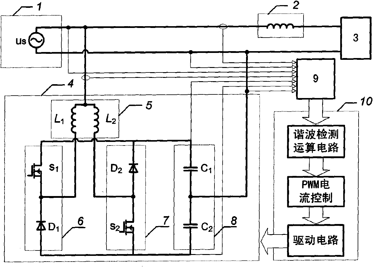
[0040] In the above-mentioned embodiment, L 1 , L 2 The inductance value is the same, the DC side is connected in series with double capacitors 8 in C 1 、C 2 The capacitance is the same; both the first bridge arm unit 6 and the second bridge arm unit 7 include a MOS transistor and a diode: the MOS transistor S in the first bridge arm unit 6 1 source and diode D 1 Cathode connected, MOS tube S 1 The drain is connected to the positive DC bus, and the diode D 1 Anode connected to negative DC bus, MOS tube S 1 and diode D 1 The connection point is parallel with the AC side of the dual inductor 5 in L 1 The input is connected; the MOS transistor S in the second bridge arm unit 7 2 Drain and Diode D 2 Anode connected, MOS tube S 2 The source is connected to the negative DC bus, and the diode D 2 The cathode is connected to the positive DC bus, and the MOS tube S 2 and diode D 2 The connection point is parallel with the AC side of the dual inductor 5 in L 2 input connec...

Embodiment 2

[0044] In the above-mentioned embodiment, L 1A , L 2A , L 1B , L 2B , L 1C , L 2C The inductance values ​​are all equal, and the DC side is connected in series with double capacitors 88 in C 1 、C 2 The capacitance is the same; both the first bridge arm unit 66 and the second bridge arm unit 77 include three MOS transistors and three diodes; in the first bridge arm unit 66, the MOS transistor S 1A , S 1B , S 1C source respectively with diode D 1A 、D 1B 、D 1C Cathode connected, MOS tube MOS tube S 1A , S 1B , S 1C The drains are all connected to the positive DC bus, and the diode D 1A 、D 1B 、D 1C The anodes are all connected to the negative DC bus, and the MOS tube S 1A and diode D 1A , MOS tube S 1B and diode D 1B , MOS tube S 1C and diode D 1C The connection points of the AC side are connected in parallel with the double inductor 5 in L 1A , L 1B , L 1CThe input is connected; in the second bridge arm unit 77, the MOS tube S 2A , S 2B , S 2C The drai...


PUM


Abstract

The invention provides a dual-buck type half-bridge parallel active power filter, belonging to the technical field of power harmonic suppression. The dual-buck type half-bridge parallel active power filter respectively comprises two types of power filter structures used for a single-phase power grid system and a three-phase four-wire system power grid system, and further comprises a bridge arm unit formed by connecting a power tube and a diode in series, parallel double inductors on an active power filter AC (Alternating Current) side, and serial double capacitors on an active power filter DC (Direct Current) side. The invention not only has the advantages of simple structure and easy control, but also can avoid the danger of the shoot-through bridge arm, simultaneously has an excellent filtering property, and can be widely applied to aviation, spaceflight, military equipment manufacture and other industries with high requirements on power supply quality of a power grid and system reliability.

Description

technical field [0001] The invention relates to a double step-down half-bridge parallel active power filter, which belongs to the technical field of power harmonic suppression and is suitable for various power systems requiring high reliability. Background technique [0002] With the rapid development of power electronic technology, especially the development of power semiconductor devices and converter technology, various power electronic devices have been widely used in various industries, but the resulting "grid pollution" has a great impact on the safety and stability of the power grid system. pose a potential threat to economic performance. Active power filters are recognized as the most effective means to comprehensively control "power grid pollution", among which parallel active filters will occupy the most mainstream position at present and in the future. Active power filters have been widely used in industrial and civil equipment in the world, and their capacity ha...

Claims


Application Information

Patent Timeline
IPC IPC(8): H02J3/01
CPCY02E40/40Y02E40/22Y02E40/20
Inventor 陈仲石磊陈淼
Owner NANJING UNIV OF AERONAUTICS & ASTRONAUTICS
Why Eureka
Try Eureka