
Key area zone setting method of capacitive screen and terminal

A capacitive screen and area technology, applied in electrical components, electronic switches, electrical digital data processing, etc., can solve the problems of "return" button press failure, low button click hit rate, small range, etc., to expand the effective pressing range, The effect of improving the hit rate of pressing and expanding the range

Active Publication Date: 2012-12-26
YULONG COMPUTER TELECOMM SCI (SHENZHEN) CO LTD
View PDF0 Cites 0 Cited by
  • Summary
  • Abstract
  • Description
  • Claims
  • Application Information

AI Technical Summary

Problems solved by technology

[0005] The inventor found in the process of implementing the present invention that the defect of the existing capacitive screen solution is that no corresponding fault-tolerant mechanism is set for each button on the capacitive screen, so that the click hit rate of the buttons is low. The reasons are as follows:
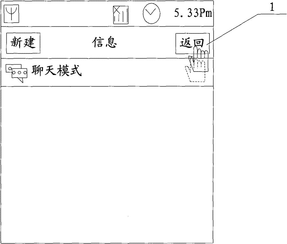
The visible area corresponding to the button on the existing capacitive screen is the pressing area, and its range is relatively small. Therefore, when the user presses the button on the capacitive screen, the contact point when pressing may be different from the button on the capacitive screen. Large deviations occur in the visible area, such as: figure 1 Among them, the visible area of ​​the "Back" button is small. When the user presses it, the contact point may be located outside the pressed area of ​​the "Back" button (that is, the visible area 1), resulting in The pressing of the "Back" button failed;
[0007] 2. The visible area of ​​the button on the existing capacitive screen is the response area, and its range is relatively small. When the user presses a button, the finger may move on the capacitive screen, for example: figure 1 In , after the finger presses the "Back" button, it moves on the capacitive screen, so that the contact point of the finger when it is lifted is offset from the response area of ​​the "Back" button (that is, the visible area 1), causing the "Back" button Failed to press the "Back" button

Method used


Image

  • Key area zone setting method of capacitive screen and terminal
  • Key area zone setting method of capacitive screen and terminal
  • Key area zone setting method of capacitive screen and terminal

Examples


Embodiment Construction

[0053] The following will clearly and completely describe the technical solutions in the embodiments of the present invention with reference to the accompanying drawings in the embodiments of the present invention. Obviously, the described embodiments are only some, not all, embodiments of the present invention. Based on the embodiments of the present invention, all other embodiments obtained by persons of ordinary skill in the art without creative efforts fall within the protection scope of the present invention.

[0054] It should be noted that the terminals described in the embodiments of the present invention may include, but are not limited to, any one or more of the following terminals: mobile phones, PDAs (Personal Digital Assistants, personal digital assistants), automatic teller machines and vehicle-mounted terminals. Unless otherwise specified, the terminal described in the embodiment of the present invention is a terminal using a capacitive touch screen.

[0055] Se...


PUM


Abstract

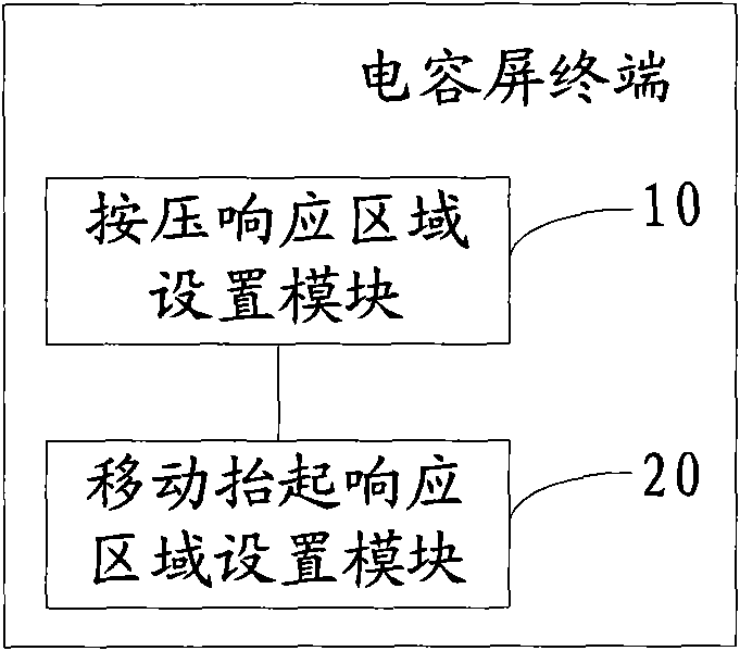
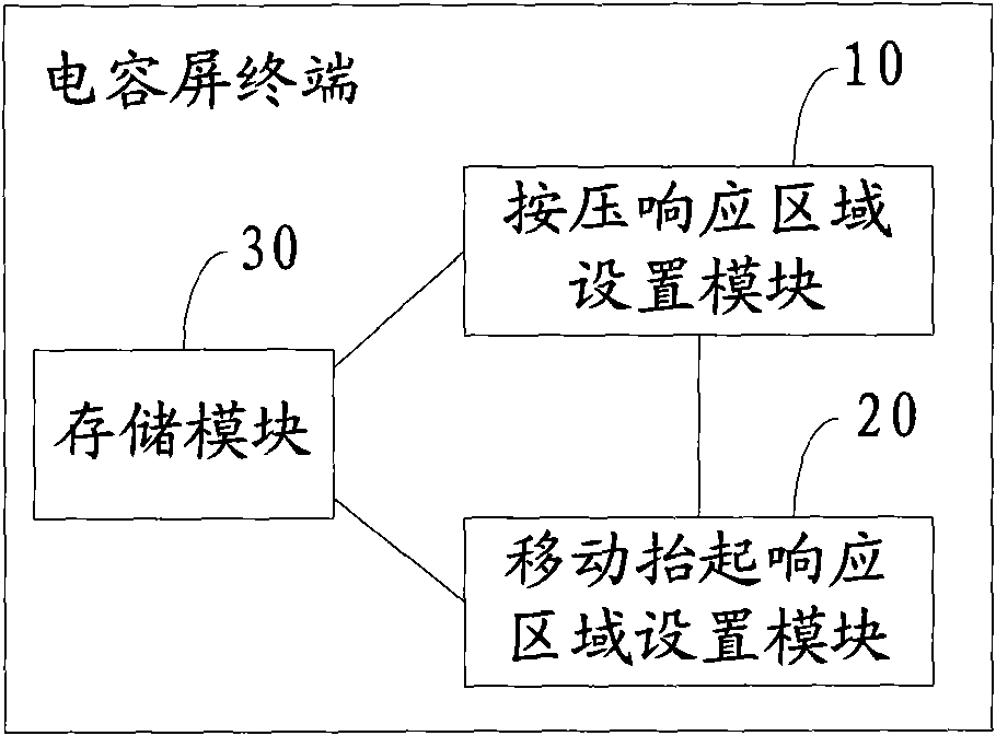
The embodiment of the invention discloses a key area setting method of a capacitive screen, which comprises the following steps: according to the preset press parameters, extending outwards along the edge of the visual area of each key on the capacitive screen to form an area, and setting the extended area as the press response area of each key; and according to the preset response parameters, extending outwards along the edge of the press response area of each key on the capacitive screen to form an area, and setting the extended area as the motion lift response area of each key. The embodiment of the invention also discloses a terminal. The invention can be used for optimizing the key area of the prior capacitive screen and setting the corresponding fault-tolerant mechanism, thereby enhancing the hit rate of the press operation on the keys and enhancing the touch experience of users.

Description

technical field [0001] The invention relates to the technical field of touch screens, in particular to a method for setting a key area of ​​a capacitive screen and a terminal. Background technique [0002] Capacitive touch screen, also known as capacitive touch screen, is mainly a layer of transparent special metal conductive substance on the glass surface. When a finger or other organism touches the metal layer, the capacitance of the contact will change. Through its capacitance value Changes in the touch position are determined to obtain touch information. Specifically, when a press operation is performed on the capacitive screen, the point with the largest capacitance value on the capacitive screen is the contact point of the press operation. [0003] The capacitive screen is a surface-contact touch screen, which is generally operated by fingers and is more sensitive than ordinary resistive screens. Each key on the capacitive screen has two areas, one of which is: the pr...

Claims


Application Information

Patent Timeline
Patent Type & Authority Patents(China)
IPC IPC(8): G06F3/044H03K17/96
Inventor 肖方旭马怡伟
Owner YULONG COMPUTER TELECOMM SCI (SHENZHEN) CO LTD
Learn More