Double-phase-locked loop circuit and control method thereof

A dual phase-locked loop and control method technology, applied in the field of phase-locked loops, can solve the problems of inability to track temperature or process, increase the complexity of circuit design, and small adjustable frequency range, so as to expand the frequency adjustment range and reduce design complexity. degree, to achieve the effect of on-chip integration

Active Publication Date: 2011-01-12
MEDIATEK INC
View PDF0 Cites 34 Cited by
  • Summary
  • Abstract
  • Description
  • Claims
  • Application Information

AI Technical Summary

Problems solved by technology

[0007] Although both methods solve the contradiction between wide frequency oscillator and narrow loop bandwidth to a certain extent, each has its own disadvantages
The disadvantage of method 1 is that the filter capacitor is too large to be integrated on-chip, so it must be designed as an off-chip capacitor, which increases the manufacturing cost
The disadvantage of method 2 is that this method cannot track changes in variables such as temperature or process
When variables such as temperature or process change, because the adjustable frequency range of the PLL control loop is small, the circuit needs to periodically switch the digital control circuit to lock the coarse frequency, which increases the complexity of the circuit design, and reduces the accuracy of the circuit

Method used


Image

  • Double-phase-locked loop circuit and control method thereof
  • Double-phase-locked loop circuit and control method thereof
  • Double-phase-locked loop circuit and control method thereof

Examples


Embodiment Construction

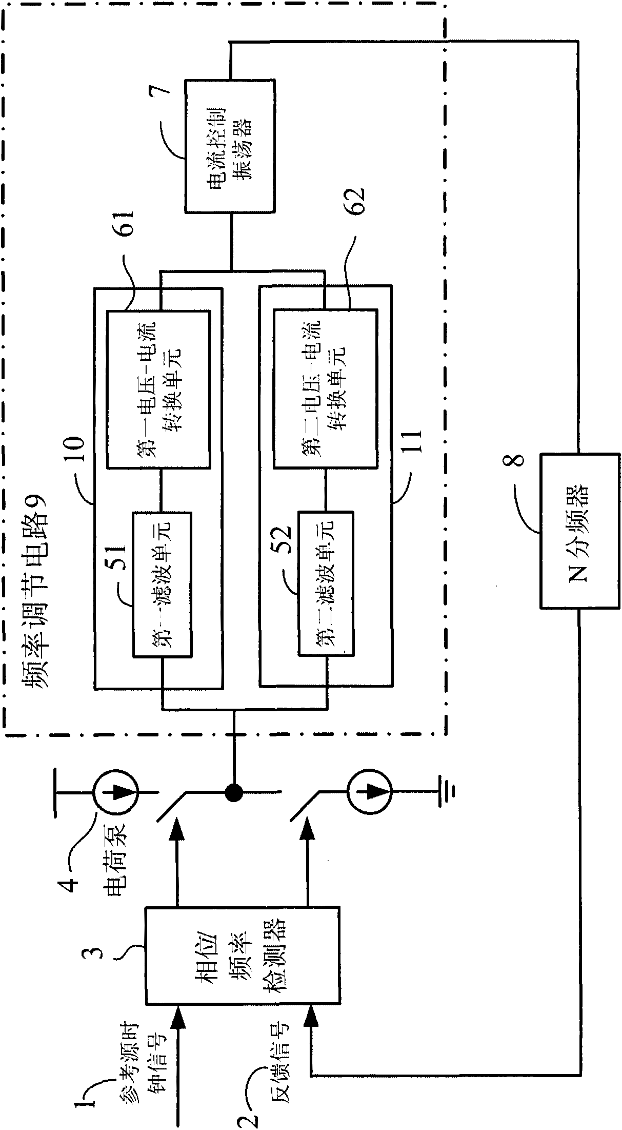
[0034] figure 2 This is a schematic diagram of the first specific embodiment of the dual phase-locked loop circuit of the present invention, and the dual phase-locked loop in the present invention refers to, but is not limited to, a high-frequency narrow-band phase-locked loop. like figure 2 As shown, in this embodiment, the dual phase-locked loop circuit includes a phase / frequency detector 3, a charge pump 4, a frequency adjustment circuit 9, an N frequency divider 8, and a reference clock coupled in sequence. Signal 1 is input to an input of the phase / frequency detector 3 . The output signal of the other end of the frequency adjustment circuit 9 generates a feedback signal 2 through the N frequency divider 8 and is input to the other input end of the phase / frequency detector 3 . The frequency adjustment circuit 9 includes a coarse adjustment circuit 10 , a fine adjustment circuit 11 and a current controlled oscillator 7 . The coarse adjustment circuit 10 is connected in...


PUM


Abstract

The invention discloses a double-phase-locked loop circuit and a control method thereof. The double-phase-locked loop circuit comprises a phase / frequency detector, a charge pump, a frequency adjustment circuit and an N frequency divider. The frequency adjustment circuit comprises a coarse adjustment circuit, a fine adjustment circuit and a current-controlled oscillator, wherein the coarse adjustment circuit is used for coarse adjustment of frequency of output signals of phase-locked loops till approaching a target frequency; the fine adjustment circuit is used for fine adjustment of the frequency of the output signals of the phase-locked loops till the target frequency; and the current-controlled oscillator is coupled with the coarse adjustment circuit and the fine adjustment circuit and used for producing the output signals of the phase-locked loops, wherein the frequency of the output signals is the target frequency. The double-phase-locked loop circuit can effectively achieve the purpose of expanding the frequency adjustment range under the situation of keeping the loop bandwidth of the phase-locked loops smaller, realize the on-chip integration and further reduce the cost and the design complexity of the circuit.

Description

technical field [0001] The present invention relates to a phase-locked loop, and more particularly, to a dual-loop phase-locked loop circuit and a control method thereof. Background technique [0002] The frequency synthesizer composed of the phase-locked loop circuit is an important realization of the clock circuit. It outputs a series of high-stability and high-precision high-frequency clock signals by inputting a high-stability and high-precision low-frequency reference frequency. [0003] figure 1 It is a schematic diagram of the structure of a general phase-locked loop circuit. The working principle of the phase-locked loop is as follows: figure 1 As shown, the phase / frequency detector 3 uses the reference clock signal 1 as a standard and compares its frequency or phase with the feedback signal 2 supplied from the output of the N divider 8. If any phase (frequency) difference is detected within its operating range, an error signal is generated, which is proportional t...

Claims


Application Information

Patent Timeline
Patent Type & Authority Applications(China)
IPC IPC(8): H03L7/08
CPCH03L7/0995H03L7/1075H03L7/093
Inventor 刘永旺卢文才史德立
Owner MEDIATEK INC
Why Eureka
Try Eureka