
Capillary network tail end water source heat pump (WSHP) central air conditioning system

A central air-conditioning system and capillary network technology, applied in air-conditioning systems, heating and ventilation control systems, heating and ventilation safety systems, etc., can solve problems such as poor room air quality, indoor air drying, and large energy consumption of fan coil systems , to achieve stable and efficient operation, reduce operating energy consumption, and solve the effects of long-term invasion

Inactive Publication Date: 2011-01-05
郑州中南科莱空调设备有限公司
View PDF7 Cites 28 Cited by
  • Summary
  • Abstract
  • Description
  • Claims
  • Application Information

AI Technical Summary

Problems solved by technology

However, at present, the all-water system is limited to the hot water heating system and the fan coil system. The fan coil system consumes a lot of energy, the fan noise is loud, occupies indoor space, and affects the interior decoration. It is easy to cause indoor air dryness during winter heating. , and it is very easy to produce cross-infection of bacteria in the air, the air quality in the room is poor, and the comfort is low
On the other hand, the temperature of the inlet and outlet water on the use side is 12-7°C during traditional cooling, and the temperature of the inlet and outlet water on the use side is 40-45°C during heating. The evaporation temperature is low, the condensation temperature is high, and the power consumption is large.

Method used


Image

  • Capillary network tail end water source heat pump (WSHP) central air conditioning system
  • Capillary network tail end water source heat pump (WSHP) central air conditioning system

Examples


Embodiment Construction

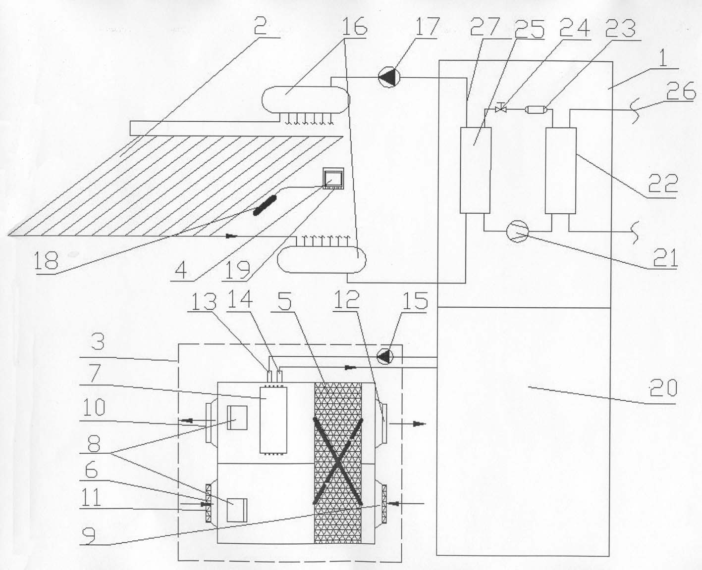
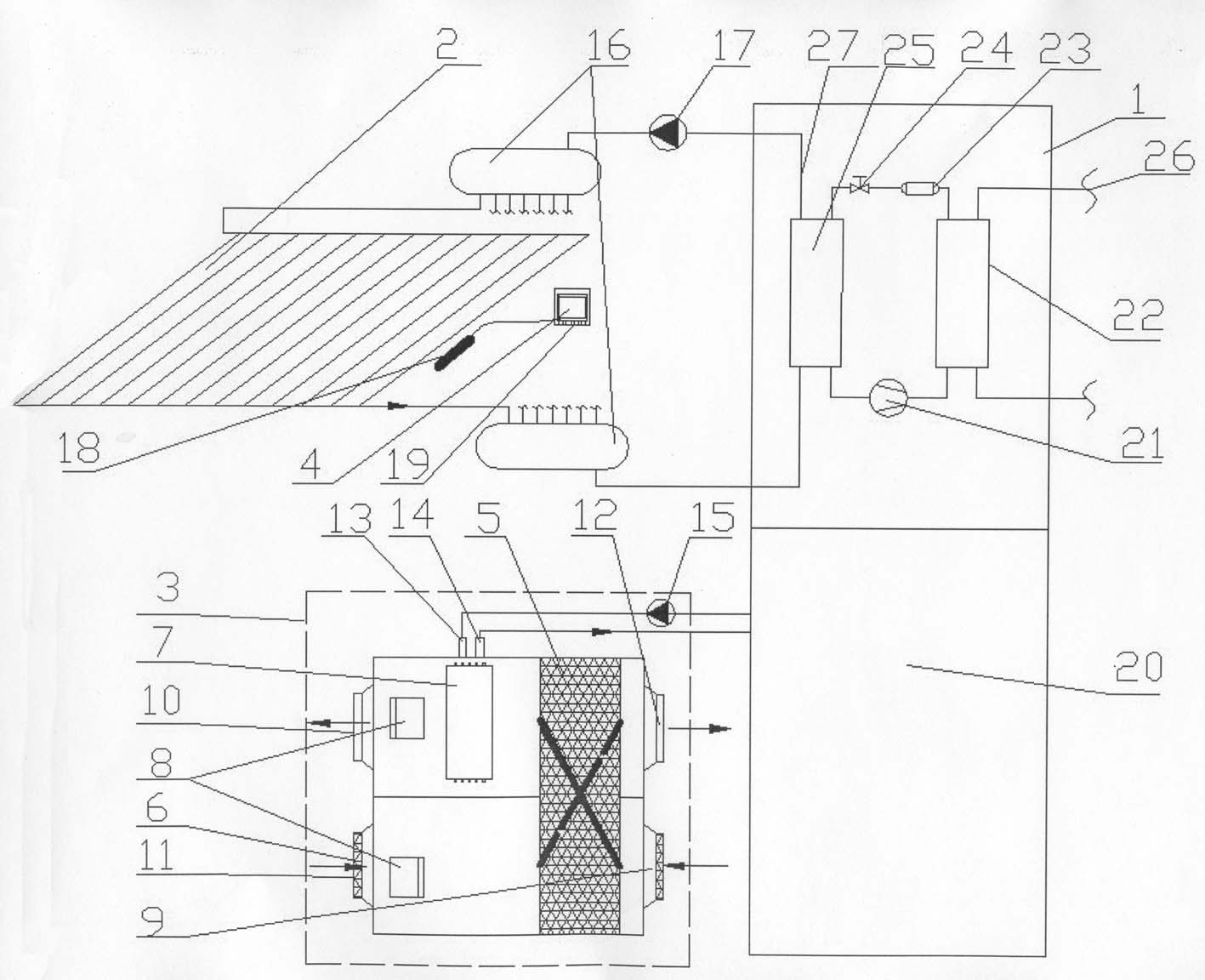
[0019] Such as figure 1 As shown, the capillary network terminal water source heat pump central air conditioning system of the present invention includes a water source heat pump unit 1, a capillary network radiation circulation system 2, a replacement fresh air dehumidification circulation system 3, and a temperature and humidity control system 4. The water source heat pump unit 1 is a special water source heat pump unit at the end of the capillary network, including a semi-hermetic screw compressor 21, a shell and tube condenser 22, a dry filter 23, an electronic expansion valve 24, a flooded evaporator 25, and a heat source side pipe 26 and use side pipe 27 . The water source heat pump unit 1 communicates with the water inlet of the capillary network radiation circulation system 2 through a circulation pump 17 and a water collector 16 . The capillary network radiation circulation system 2 is a capillary network for radiation composed of random copolymerized polypropylene P...


PUM


Abstract

The invention discloses a capillary network tail end water source heat pump (WSHP) central air conditioning system, comprising a water source heat pump (WSHP) set, a capillary network radiation cyclic system, a replacement fresh air dehumidification cyclic system and a temperature and humidity control system, wherein the WSHP set is communicated with the water inlet of the capillary network radiation cyclic system via a circulating pump, a water collector and a water segregator; external cold and heat sources are communicated with the inner cavity of a surface cooler via a circulating pump and a water inlet orifice, and go back via a water outlet orifice; and fresh air is communicated with an indoor air outlet through the surface cooler after heat exchange is realized between the refresh air and indoor return air via a plate heat exchanger. The invention has the advantages of higher temperature of cold water in summer, lower temperature of hot water in winter, high unit efficiency, stable and efficient operation, lowered operation energy consumption, reduced transmission and distribution energy consumption, high efficiency of transmitting cold and heat quantities, even temperature distribution and little noise, and a tail end system is provided with no moving parts and has the functions of refrigeration, heating, dehumidification and air circulation and satisfies the requirement of the indoor fresh air supply all the year round.

Description

technical field [0001] The invention relates to a central air-conditioning system, in particular to a water-source heat pump central air-conditioning system at the end of a capillary network. Background technique [0002] Traditional indoor heating and air conditioning generally adopt the form of air-water system, all-air system, refrigerant system and all-water system; compared with other forms, the all-water system has many advantages, 1. Low energy transmission and space occupation Small; 2. Flexible and convenient to use; 3. Prevent air cross-infection; 4. Except for the cold and heat source computer room, no other computer rooms are needed, and the occupied building area is small. However, at present, the all-water system is limited to the hot water heating system and the fan coil system. The fan coil system consumes a lot of energy, the fan noise is loud, occupies indoor space, and affects the interior decoration. It is easy to cause indoor air dryness during winter he...

Claims


Application Information

Patent Timeline
IPC IPC(8): F24F3/147F24F11/02F24F13/30
Inventor 梁年良郭其峰张文全韩东方杨文博李卫金林田杨新明
Owner 郑州中南科莱空调设备有限公司
Learn More