
Light emitting diode module

一种发光二极管、模组的技术,应用在发光元件的半导体器件、光源、电光源等方向,能够解决路面均匀照度差、影响行车安全、亮暗不均等问题

Inactive Publication Date: 2011-01-05
FU ZHUN PRECISION IND SHENZHEN +1
View PDF2 Cites 9 Cited by
  • Summary
  • Abstract
  • Description
  • Claims
  • Application Information

AI Technical Summary

Problems solved by technology

However, the illuminance directly under the lamp is high, and the illuminance in other areas is low, which still leads to poor uniform illuminance on the road surface. This uneven lighting directly affects driving safety.

Method used


Image

  • Light emitting diode module
  • Light emitting diode module
  • Light emitting diode module

Examples


Embodiment Construction

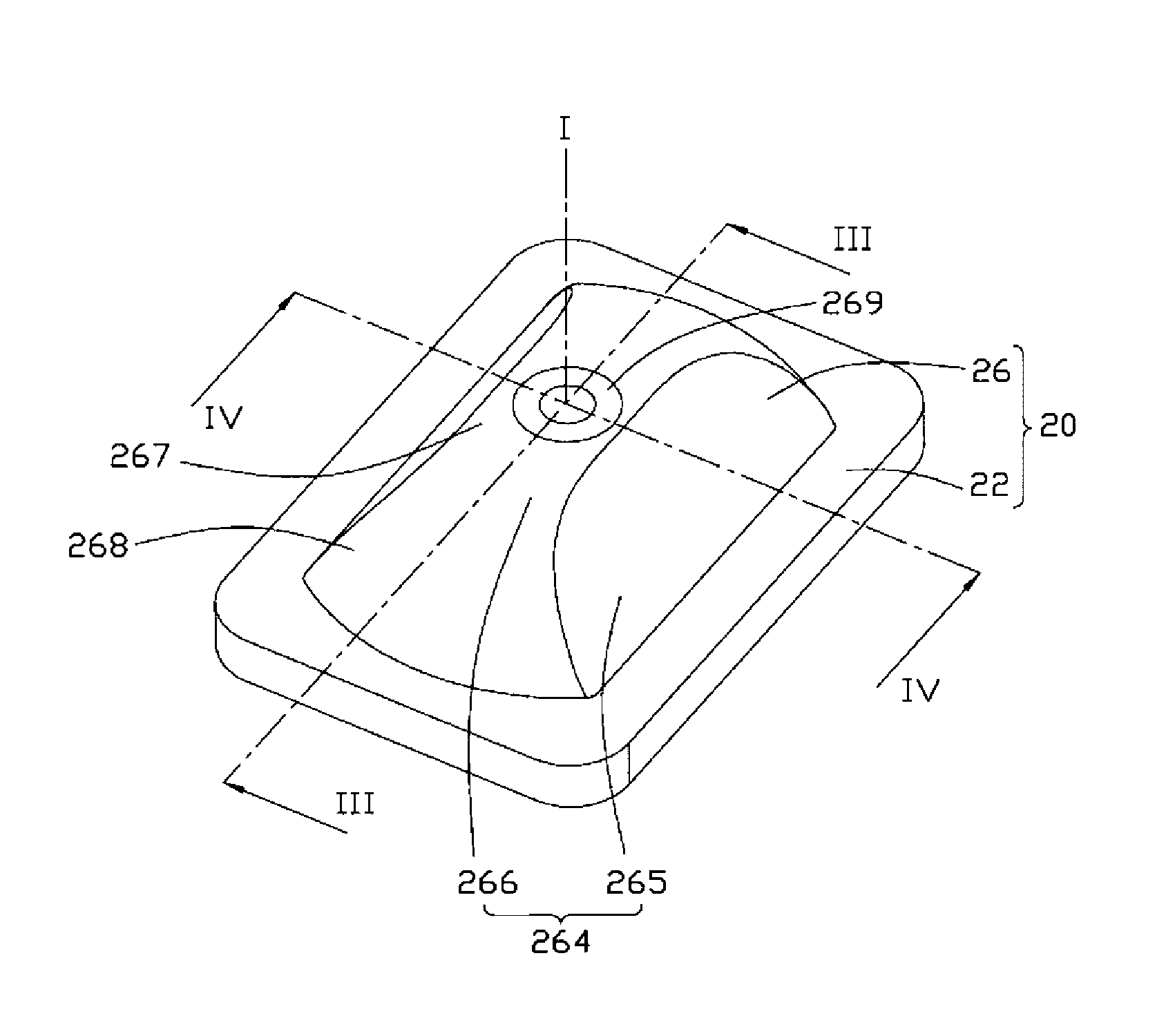
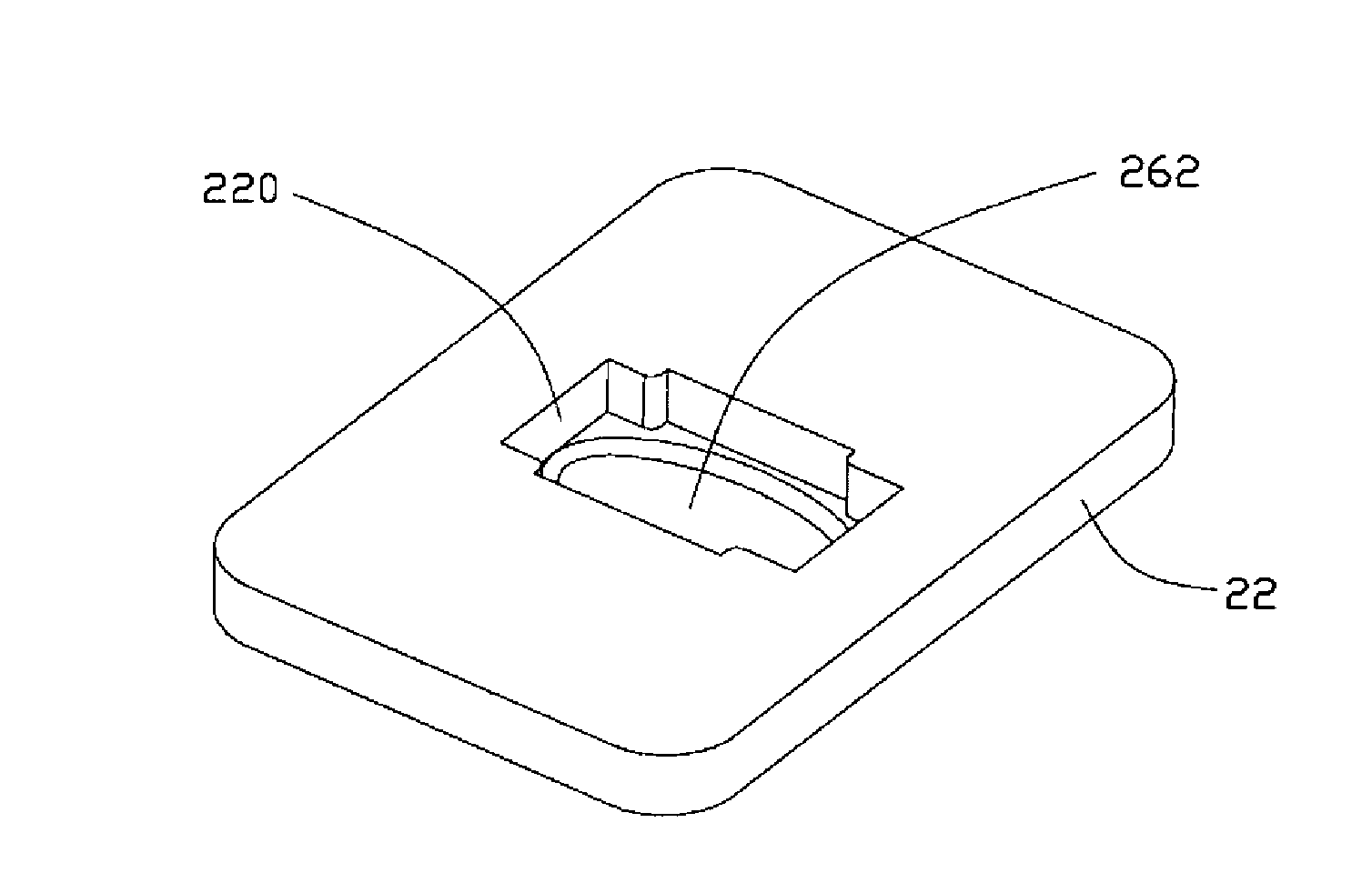
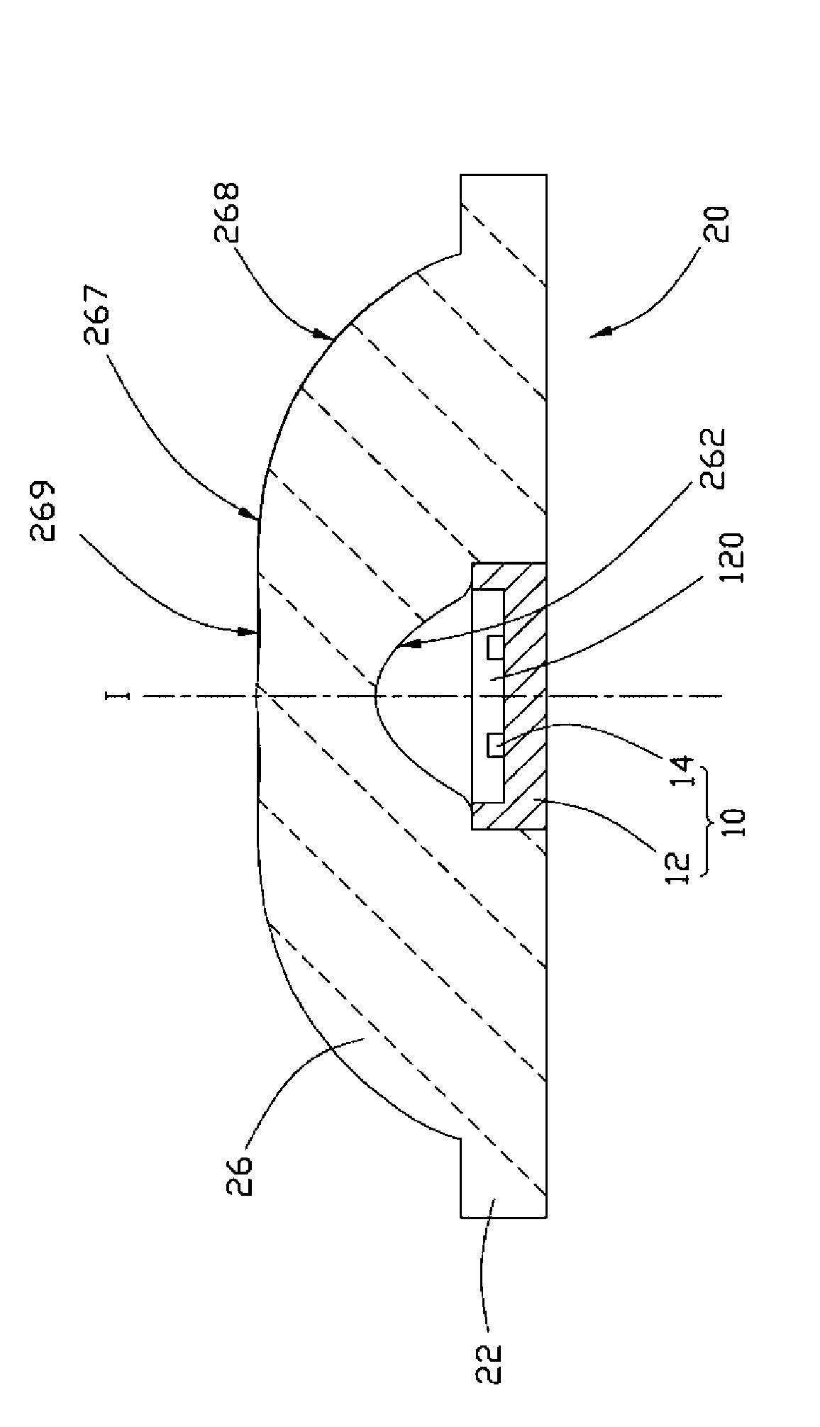
[0013] Such as Figure 1-4 As shown, the LED module according to one embodiment of the present invention includes a LED 10 and a lens 20 covering the LED 10 .

[0014] The LED 10 includes a rectangular base 12 with a groove 120 and a plurality of LED chips 14 fixed in the groove 120 . The light emitting diode 10 can be provided with different numbers of light emitting diode chips 14 according to different power requirements.

[0015] The lens 20 is integrally molded from a transparent material with excellent optical performance, such as PMMA or PC plastic. The lens 20 has an optical axis I passing through its central point. The lens 20 has a symmetrical structure. Specifically, the lens 20 is symmetrical along the first plane passing through the optical axis I along its length direction, and the first plane is image 3 The plane in which the section shown is. The lens 20 is symmetrical along the second plane passing through the optical axis I in its width direction, and th...


PUM


Abstract

The invention discloses a light emitting diode module, comprising a light emitting diode and a lens matched with the light emitting diode. The lens is provided with an optical shaft, a light incident surface and a light emergent surface, wherein the light incident surface and the light emergent surface are used for the incidence and the emergence of the light rays emitted by the light emitting diode, the light incident surface is concave inwards, the light emergent surface is convex outwards, the leans is symmetric respectively along a first plane and a second plane which are vertical to and intersected with the optical shaft, in the first plane, peak intensity of the light rays emitted from the lens is in a range deviating the optical shaft by 68-78 degrees, and in the second plane, the peak intensity of the light rays emitted from the leans is in a range deviating the optical shaft by 0-22 degrees. By using the lens to adjust the light rays of the light emitting diode, the light emitting diode module can generate an optical shape with a large illumination range along one direction and a small illumination range along the other direction, thereby being suitable to the illumination in special occasions such as roads and the like.

Description

technical field [0001] The invention relates to a light emitting diode module, in particular to a light emitting diode module for lighting. Background technique [0002] As an emerging light source, light-emitting diodes have been widely used in various fields due to their advantages of high luminous efficiency, small size, light weight, and environmental protection, and are likely to replace traditional light sources. [0003] Existing light-emitting diode lamps usually cover the light-emitting diode with a lens to gather light, but the shape of light projected by the lens is circular, and the light intensity difference between the center and the periphery is too large. In addition, for some occasions that require large-scale lighting in one direction and small-scale lighting in another direction, such as road lighting, a wide range of illumination is required in the direction of road extension, good lighting effects, and large angle requirements; and There is no need for ...

Claims


Application Information

Patent Timeline
Patent Type & Authority Applications(China)
IPC IPC(8): F21S2/00F21V5/04F21Y101/02
CPCF21Y2101/02F21V5/04F21Y2115/10
Inventor 张海卫吕佳川
Owner FU ZHUN PRECISION IND SHENZHEN
Learn More