
Air-suspending T-shaped rail slider

An air suspension and rail technology, applied in the field of rail systems, can solve the problems of equipment accuracy decline, air gap changes, affecting measurement and machining accuracy, etc., and achieve the effect of avoiding force deformation

Inactive Publication Date: 2011-01-05
XIAMEN UNIV
View PDF9 Cites 11 Cited by
  • Summary
  • Abstract
  • Description
  • Claims
  • Application Information

AI Technical Summary

Problems solved by technology

There are fluctuations in the airflow in the setting of the air outlet, the movement of the slider is not stable enough, and the friction is relatively large, resulting in a decrease in the accuracy of the equipment
In addition, the composition of the slider is usually composed of four different plane panels. Under the action of unbalanced force during air injection, it is easy to cause changes in the air gap, and the air flotation effect is not good, which affects the measurement and processing accuracy.

Method used


Image

  • Air-suspending T-shaped rail slider
  • Air-suspending T-shaped rail slider
  • Air-suspending T-shaped rail slider

Examples


Embodiment Construction

[0016] The present invention will be further described below in conjunction with drawings and embodiments.

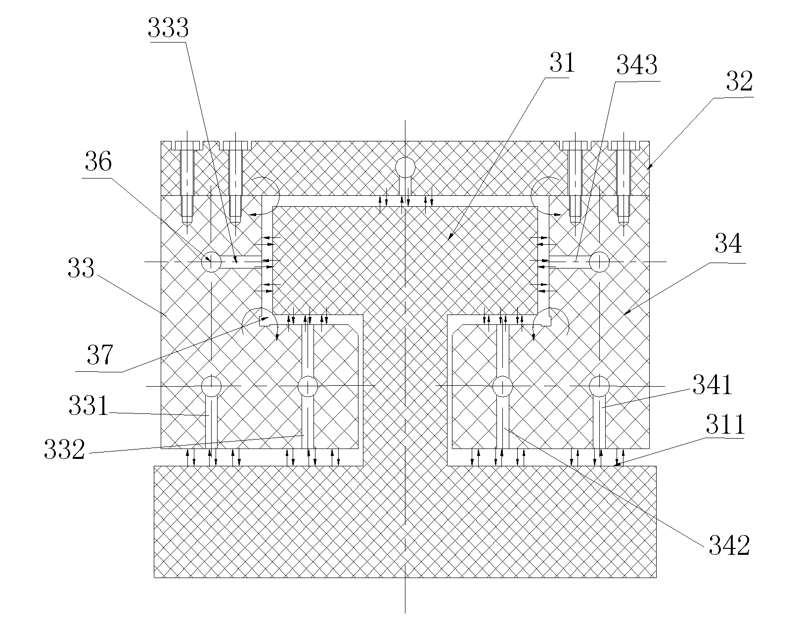
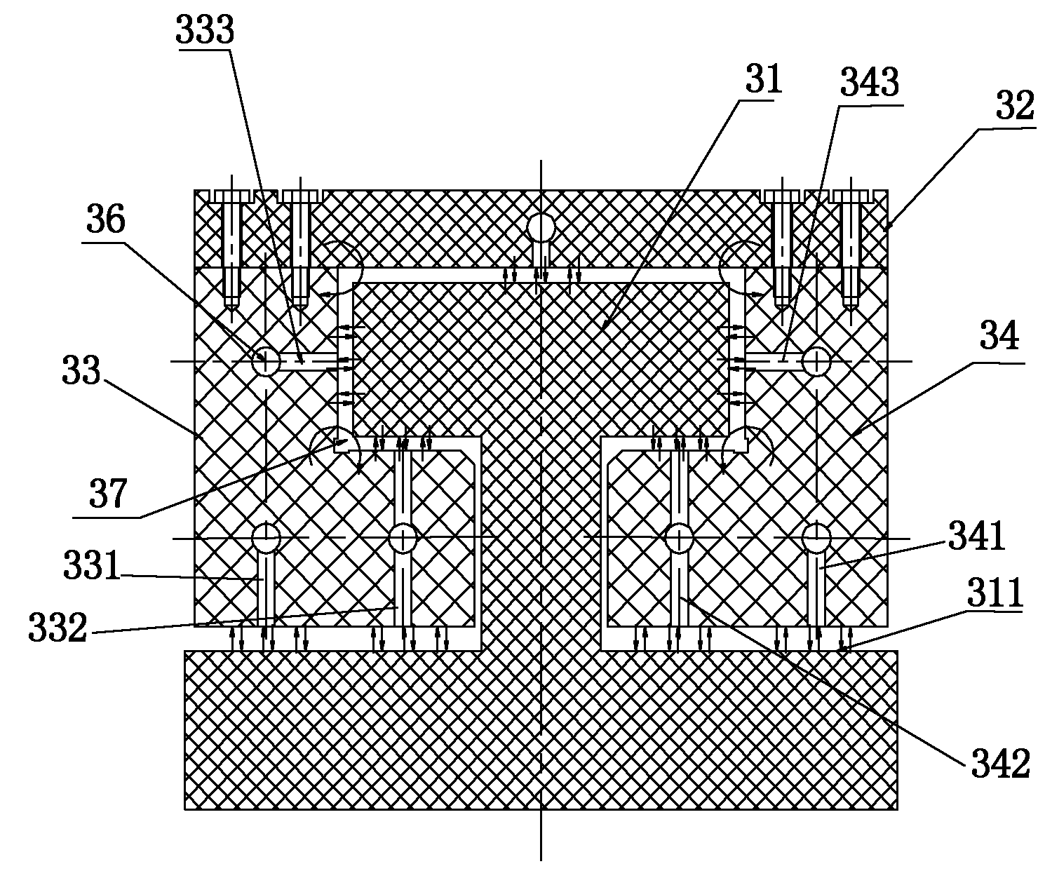
[0017] see figure 2 , the embodiment of the present invention is provided with upper panel 32, left panel 33 and right panel 34, and left panel 33 and right panel 34 are all L-shaped panels, and the lower side panel part of left panel 33 is provided with for blowing to guide rail base surface 311. The one-way air hole 331 and the two-way air hole 332 of air are provided with the one-way air hole 333 on the upper side panel part of the left panel 33; 341 and two-way air hole 342, the upper side panel part of right panel 34 is provided with one-way air hole 343. exist figure 2 Among them, mark 36 is the gas pipeline, and 37 is the gap between gas films.

[0018] The connection mode between the panels of the existing slider depends on the material and size, and is usually bolted or connected by other methods such as chemical agent gluing.

[0019] In the improved str...


PUM


Abstract

The invention provides an air-suspending T-shaped rail slider, relating to a rail system and providing an air-suspending T-shaped rail slider capable of effectively overcoming unstable structure problem occurred at the time of air-suspending movement and reducing friction interference in the system. The slider comprises a top panel, a left panel and a right panel, wherein the left panel and the right panel are L-shaped plates; the lower part of the left panel is partially provided with at least one air hole for blowing a guide rail base surface; the lower part of the right panel is partially provided with at least one air hole for blowing the guide rail base surface; and at least one air hole for blowing the guide rail base surface is an one-way air hole or / and an two-way air hole.

Description

technical field [0001] The invention relates to a track system, in particular to an air suspension T-shaped track slider. Background technique [0002] The main part of the air-suspension guide rail system is composed of guide rails and sliders that are structurally matched with them. Its working principle is: the airflow is ejected through the air outlet on the guide rail or the slider, and a stable air film is formed between the surface of the guide rail and the slider to suspend the slider on the guide rail, reducing or eliminating the contact between the slider and the slider. The contact friction between the rails makes the movement of the slider close to the ideal frictionless movement. Air suspension devices are generally divided into two types: guide rail air outlet type and slider air outlet type. Among them, the air outlet type of the guide rail is drilled with many small holes on the guide rail, and the air is ejected from the air pipe in the guide rail through ...

Claims


Application Information

Patent Timeline
IPC IPC(8): E01B25/32
Inventor 张建寰刘志强胡振邦
Owner XIAMEN UNIV
Learn More