


Quick Research
Generate reliable direction feasibility study reports for your R&D in just a few steps.

Technical Q&A
Discover and master advanced knowledge NOW. Basics, ideas, possibilities, all at once.

Find Solutions
As an expert in R&D theories, this can generate solutions to your technical problems instantly.

Evaluate Feasibility
Analyze your overall solution with one click, know your potential R&D risks in advance.

Monitor Landscape
Get weekly tech updates, stay abreast of the latest tech innovations and key insights.
Induction heating device
A technology of induction heating device and heating coil, which is applied in the direction of induction heating device, induction heating, household cooking utensils, etc., to achieve the effect of ingenious conception, reduced interference, accurate and stable temperature measurement
- Summary
- Abstract
- Description
- Claims
- Application Information
AI Technical Summary
Problems solved by technology
Method used
Image

Examples
no. 1 example
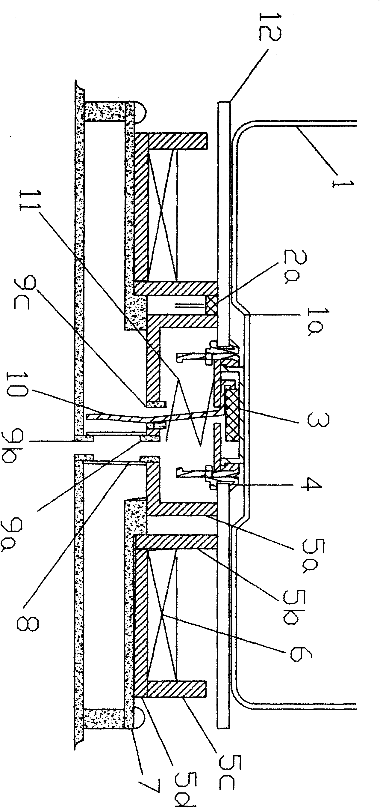
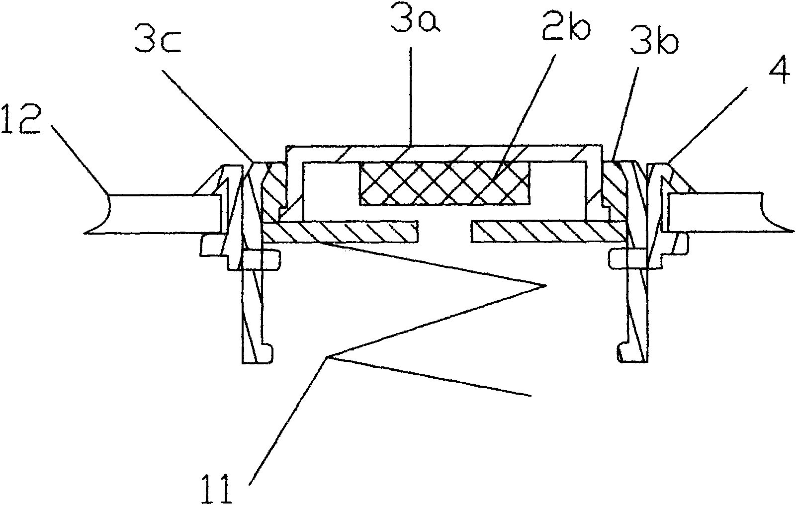
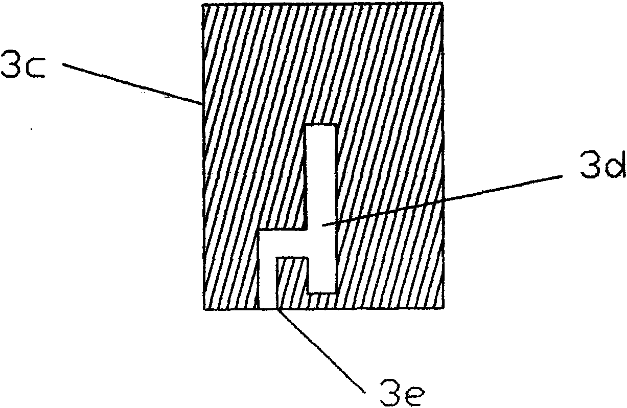
[0054] Such as figure 1 , figure 2 , image 3 and Figure 4 The induction heating device shown includes: a cooking container 1, a panel 12 under it, a temperature sensing probe 3 disposed in the middle of the panel 12, and a cup-shaped first shielding ferrite 5a between the temperature sensing probe 3 and the heating coil 6 , the ring-shaped second shielding ferrite 5b, the second energy-shaping ferrite 5d below the heating coil 6 and the first energy-shaping ferrite 5c outside. Among them, the heating coil 6 is arranged on the plastic mounting bracket 7 under it, and the middle part of the mounting bracket 7 also provides support for the bottom of the first shielding ferrite 5a; Bar ferrite surrounds, and it and the second energy-shaping ferrite 5d and the first energy-shaping ferrite 5c jointly form the structure that section is " U " shape; The sensitive resistor 2a; the bottom of the first shielding ferrite 5a is provided with a wire outlet hole 9c and a drain hole 9a...
no. 2 example
[0059] Such as Figure 5 and Image 6 The shown induction heating device comprises: a cooking container 1, a panel 12 under it, a temperature-sensing probe arranged in the middle of the panel 12, a cup-shaped first shielding ferrite 5a between the temperature-sensing probe and the heating coil 6, a ring The second shielding ferrite 5b, the second energy-shaping ferrite 5d below the heating coil 6 and the first energy-shaping ferrite 5c outside. Wherein, the heating coil 6 is arranged on the plastic mounting bracket 7 under it, and the middle part of the mounting bracket 7 also provides support for the bottom of the first shielding ferrite 5a; Bar ferrite surrounds, and it and the second energy-shaping ferrite 5d and the first energy-shaping ferrite 5c jointly form the structure that section is " U " shape; The sensitive resistor 2a; the bottom of the first shielding ferrite 5a is provided with a connecting rod outlet hole 9d and a drain hole 9a, and the drain hole 9a communi...
PUM
 Abstract
Description
Claims
Application Information
 - R&D Engineer
- R&D Manager
- IP Professional
- Industry Leading Data Capabilities
- Powerful AI technology
- Patent DNA Extraction
Browse by: Latest US Patents, China's latest patents, Technical Efficacy Thesaurus, Application Domain, Technology Topic, Popular Technical Reports.
© 2024 PatSnap. All rights reserved.Legal|Privacy policy|Modern Slavery Act Transparency Statement|Sitemap|About US| Contact US: help@patsnap.com