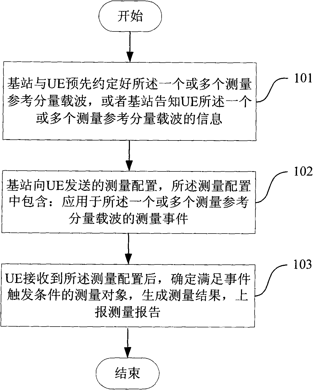
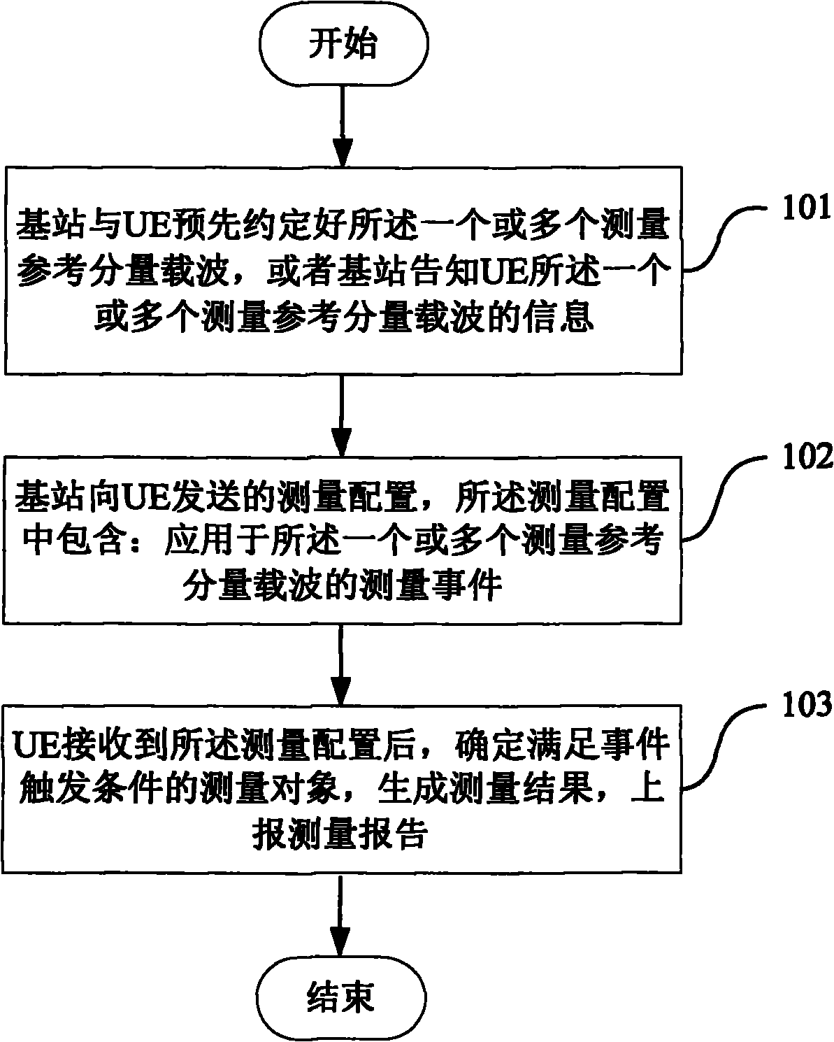
Method for processing measurement configuration in carrier aggregation
A processing method and measurement configuration technology, applied in network traffic/resource management, electrical components, wireless communication, etc., can solve the problem that measurement configuration cannot be applied to multi-carriers, and achieve the effect of meeting the needs of mobility
- Summary
- Abstract
- Description
- Claims
- Application Information
AI Technical Summary
Problems solved by technology
Method used
Image
Examples
application example 1
[0086] In the LTE Advance system, the schematic diagram of its network layout can be found in figure 2 , there is an S1 interface between the core network and the base station (macro base station), and there is an X2 interface between adjacent base stations; the home base station can be directly connected to the core network, or can be connected to the core network through the home base station gateway. There is no X2 interface between the home base station and the macro base station. The UE is located in a carrier aggregation cell managed by the macro base station and is in an idle state. The component carriers included in the carrier aggregation cell are three consecutive 20MHz component carriers within the frequency band 1 (Band1, uplink UL 1920-1980MHz, downlink DL 2110-2170MHz). These three carriers all send system messages and paging messages.
[0087] At a certain moment, the UE initiates random access on component carriers (UL 1920-1940, DL 2110-2130), and successfu...
application example 2
[0096] In the LTE Advance system, the schematic diagram of its network layout can be found in figure 2 , there is an S1 interface between the core network and the base station (macro base station), and there is an X2 interface between adjacent base stations; the home base station can be directly connected to the core network, or can be connected to the core network through the home base station gateway. There is no X2 interface between the home base station and the macro base station. The UE is located in a carrier aggregation cell managed by the home base station and is in an idle state. The carrier aggregation cell contains component carriers in frequency band 1 (Band 1, UL 1920~1980MHz, DL 2110~2170MHz) and frequency band 2 (Band 2, UL 1850~1870MHz, DL 1930~1950). A discontinuous 20MHz component carrier. Among the four carriers, only three component carriers in Band 1 send system messages and paging messages.
[0097] At a certain moment, the UE initiates random access ...
application example 3
[0109] In the LTE Advance system, the schematic diagram of its network layout can be found in figure 2 , there is an S1 interface between the core network and the base station (macro base station), and there is an X2 interface between adjacent base stations; the home base station can be directly connected to the core network, or can be connected to the core network through the home base station gateway. There is no X2 interface between the home base station and the macro base station. The UE is located in a carrier aggregation cell managed by the base station and is in an idle state. The carrier aggregation cell contains component carriers in frequency band 1 (Band1, UL 1920~1980MHz, DL 2110~2170MHz) and frequency band 2 (Band 2, UL1850~1870MHz, DL 1930~1950), which are 4 different Continuous 20MHz component carrier. Among the four carriers, only one component carrier in Band 1 (UL 1920-1940, DL2110-2130) sends system messages and paging messages, and this carrier is also c...
PUM
 Abstract
Description
Claims
Application Information
 - R&D
- Intellectual Property
- Life Sciences
- Materials
- Tech Scout
- Unparalleled Data Quality
- Higher Quality Content
- 60% Fewer Hallucinations
Browse by: Latest US Patents, China's latest patents, Technical Efficacy Thesaurus, Application Domain, Technology Topic, Popular Technical Reports.
© 2025 PatSnap. All rights reserved.Legal|Privacy policy|Modern Slavery Act Transparency Statement|Sitemap|About US| Contact US: help@patsnap.com


