
Circular cooler air inlet system

A technology of air intake system and ring cooler, which is applied in mechanical equipment, engine components, engine sealing, etc., can solve the problems of temperature difference between the two sides of the spacer, difficulty in ensuring reliability, and limited strength, so as to ensure normal operation, The effect of preventing vaporization and speeding up

Active Publication Date: 2012-06-06
ZHONGYE-CHANGTIAN INT ENG CO LTD
View PDF0 Cites 0 Cited by
  • Summary
  • Abstract
  • Description
  • Claims
  • Application Information

AI Technical Summary

Problems solved by technology

However, one of the power sources to promote the air flow in the partition layer is natural air flow, and the other is the temperature difference between the two side walls of the spacer, but the strength is limited, and the reliability is difficult to guarantee. Therefore, it is necessary to increase the width of the partition or other measures to increase the convection of the partition. Mobility of hot air

Method used


Image

  • Circular cooler air inlet system
  • Circular cooler air inlet system
  • Circular cooler air inlet system

Examples


Embodiment Construction

[0044]The invention provides an air intake system of a ring cooler, which can prevent the liquid in the annular liquid tank from vaporizing, and provide a power source for pushing the air flow in the double wall sleeve.

[0045] In order to facilitate the understanding of those skilled in the art, the structure and working principle of the air inlet system of the annular cooler according to the present invention will be described in detail below with reference to the accompanying drawings.

[0046] see Figure 4 , which is a structural diagram of the air intake system of the annular cooler according to the embodiment of the present invention.

[0047] The air inlet system of the annular cooler in the embodiment of the present invention includes an annular air duct 31, which is connected to a branch air duct 32 of the annular air duct 31, and the branch air duct 32 is connected to an annular air duct 33, and the annular air duct 33 Each outlet of each outlet is connected to th...


PUM


Abstract

The invention discloses a circular cooler air inlet system, which comprises a circular air pipe and a branch air pipe communicated with the circular air pipe and a circular air flue, wherein the outlet of the circular air flue is communicated with the blast pipe of a trolley; a gantry sealing device is connected on the blast pipe of the trolley, the cover plate thereof is covered on a circular trough, and a gantry air flue inner ring plate and a gantry air flue outer ring plate thereof extend downwards below the liquid level of the circular trough; the outlet of the circular trough is arranged on the baseplate of the circular air flue trough in a normal temperature pressure air cooling region of the circular cooler; the circular trough is in a double-layer wall jacket structure both in the circular air flue trough inner ring plate and in the circular air flue trough outer ring plate at the high temperature region of the circular cooler; a pore plate is arranged in each double-layer wall jacket; and the pore plate is provided with a pipeline communicated with a normal temperature pressure air outlet. The circular cooler air inlet system provided by the invention can prevent liquid in the circular trough from being vaporized and can provide power source for pushing air flow in the double-layer wall jacket.

Description

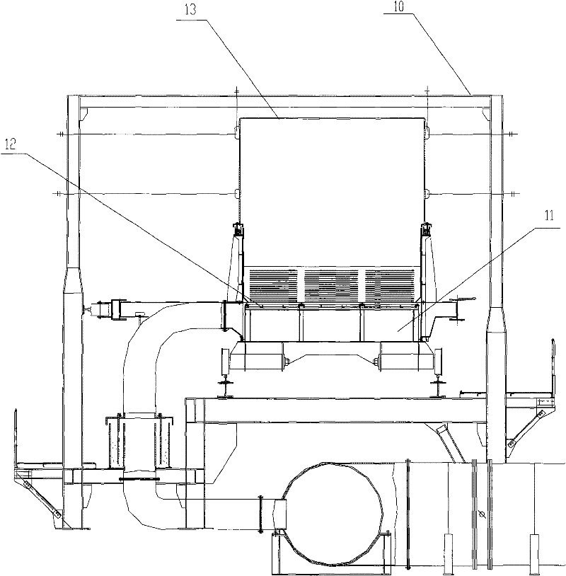
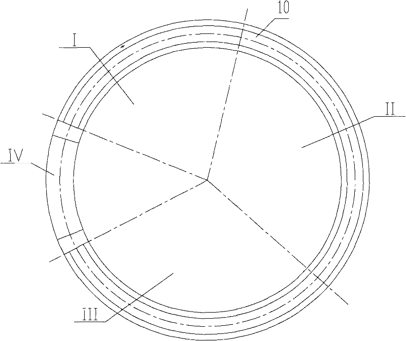
technical field [0001] The invention relates to an annular cooler, in particular to an air inlet system of an annular cooler. Background technique [0002] In iron and steel smelting, ring coolers are used to cool sintered materials. The ring cooler is in the shape of a ring as a whole, and the sintered material runs in the ring cooler for a week through a trolley to complete cooling and unloading. see figure 1 , is the radial (pointing to the center of the annular cooler) cross-sectional view of the annular cooler 10, the sintered material is laid on the grate plate 12 of the trolley 11, and the trolley 11 rotates at a constant speed around the center of the annular cooler 10. At the same time, the cold air blown by the blower (not shown in the figure) passes through the grate plate 12 from bottom to top and enters the trolley. . [0003] see figure 2 , is the overall schematic diagram of the annular cooler 10, and the annular cooler 10 is divided into a high temperat...

Claims


Application Information

Patent Timeline
Patent Type & Authority Patents(China)
IPC IPC(8): F27D15/02F16J15/40
Inventor 高德亮戴传德周慧玲
Owner ZHONGYE-CHANGTIAN INT ENG CO LTD
Learn More