
Solar-air dual-heat-source heat pump water heater

A heat pump water heater and solar energy technology, which is applied to solar thermal power generation, solar thermal devices, fluid heaters, etc., can solve problems such as easy failure and complex heat pump structure, improve reliability, simplify the structure of heat exchangers, and realize comprehensive Effective use of the effect

Inactive Publication Date: 2010-12-29
ZHONGYUAN ENGINEERING COLLEGE
View PDF9 Cites 2 Cited by
  • Summary
  • Abstract
  • Description
  • Claims
  • Application Information

AI Technical Summary

Problems solved by technology

[0005] The purpose of the present invention is to provide a solar-air dual heat source heat pump water heater. The solar-air dual heat source heat pump water heater should solve the technical problems of the solar-air heat source heat pump in the prior art with complex structure and easy failure.

Method used


Image

  • Solar-air dual-heat-source heat pump water heater
  • Solar-air dual-heat-source heat pump water heater
  • Solar-air dual-heat-source heat pump water heater

Examples


Embodiment 1

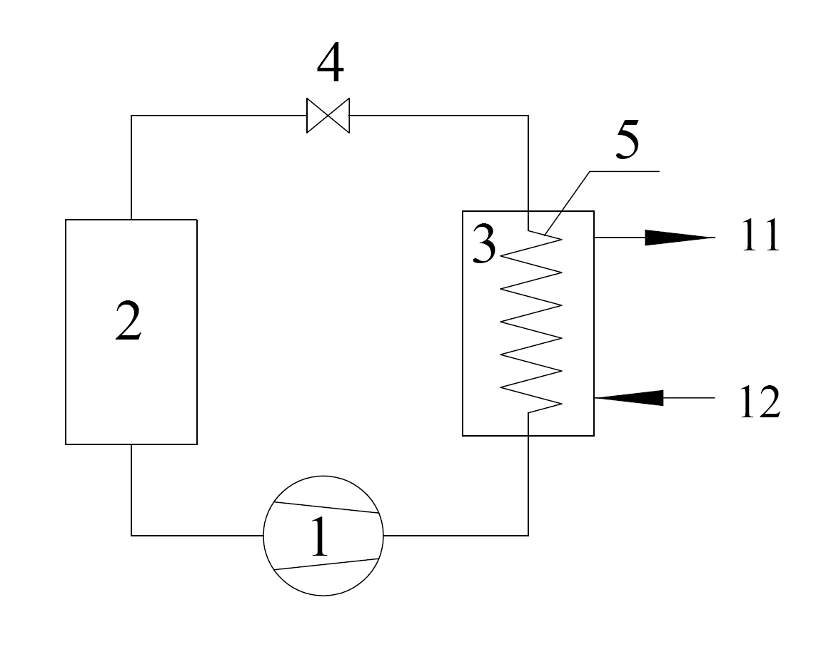
[0023] Such as figure 1 , figure 2 , image 3 with Figure 4 as shown, figure 1 The water supply pipeline, the hot water supply pipeline and the necessary valve assembly are omitted. In this embodiment, the solar-air dual heat source heat pump water heater includes a compressor 1, a solar-air dual heat source heat exchanger 2, a storage Hot water tank 3, throttle valve 4, hot water heat exchange coil 5 and connecting pipelines. The specific connection relationship between its various components is as follows: one interface of the solar-air dual heat source heat exchanger 2 and one interface of the heat exchange coil 5 are connected through the compressor 1, and the other interface of the solar-air dual heat source heat exchanger 2 One interface and the other interface of the heat exchange coil 5 are connected through the throttle valve 4; the heat exchange coil 5 is placed in the heat storage tank 3, and the heat storage tank 3 is provided with a water supply port and a h...

Embodiment 2

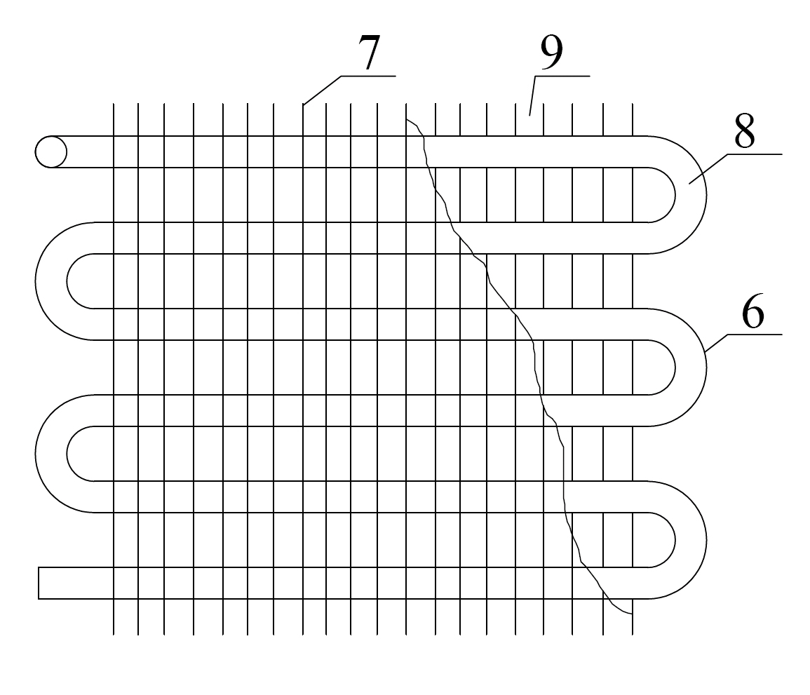
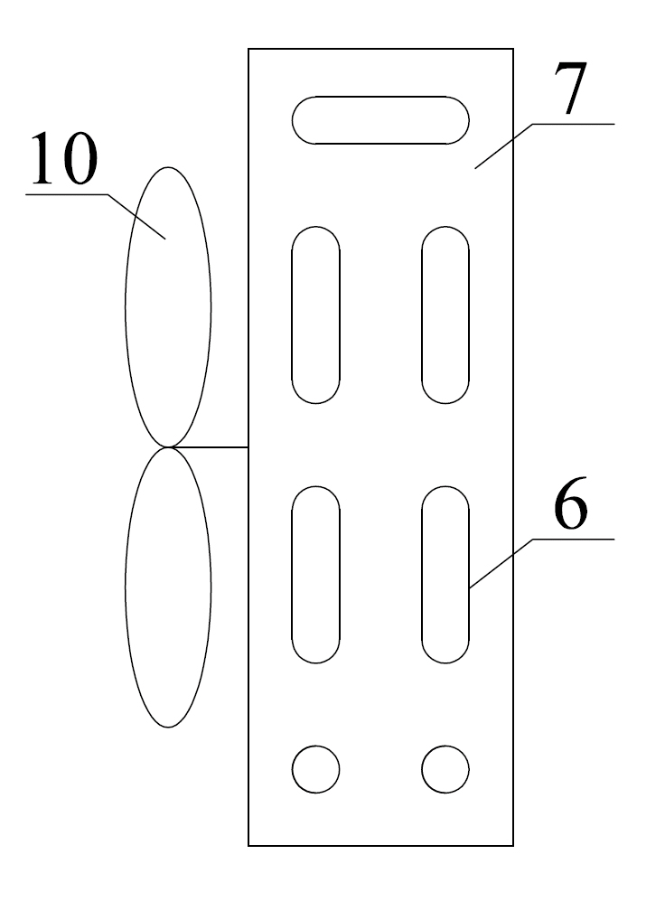
[0028] Such as figure 1 , Figure 5 , Image 6 with Figure 7 As shown, the difference between this embodiment and Embodiment 1 is that the solar-air dual heat source heat exchanger is a fin-wound structure, the heat exchange tube 6 is bent in an S shape, and a plurality of annular fins 7 are set On the outside of the heat exchange tube, the upper and lower adjacent layers of fins are separated structures, and the single fins of the upper and lower adjacent layers of fins are aligned up and down to form an air flow channel.

[0029] In addition to the above-mentioned solutions, the multiple structures of the present invention can also be modified in many ways. For example, the shape of the solar-air dual heat source heat pump water heater can also adopt other forms, not necessarily a square, which can be obtained by changing the shape of the fins in Embodiment 1 and the arrangement of the fins in Embodiment 2. At the same time, The fins can also be set in a certain shape t...


PUM


Abstract

The invention discloses a solar-air dual-heat-source heat pump water heater. The water heater comprises a compressor, a heat exchanger, a hot water storage tank, a throttle valve, a hot water heat exchanging coil pipe and a connecting pipeline, wherein the heat exchanger is a solar-air dual-heat-source heat exchanger; one port of the solar-air dual-heat-source heat exchanger is connected with one port of the hot water heat exchanging coil pipe through the compressor, while the other port is connected with the other port of the hot water heat exchanging coil pipe through the throttle valve; the hot water heat exchanging coil pipe is arranged in the hot water storage tank; and the solar-air dual-heat-source heat exchanger comprises a heat exchanging pipe, fins combined with the outer wall of the heat exchanging pipe, and a solar radiation absorbing coating on the external surfaces of the heat exchanging pipe and the fins. The water heater can obviously improve the heating coefficient of performance (COP) and the running stability thereof and simplify the system composition by simultaneously using the air source and the solar radiation energy as the heat pump heat source.

Description

technical field [0001] The invention relates to a solar utilization device, in particular to a heat pump device utilizing solar energy, in particular to a solar-air dual heat source heat pump water heater. Background technique [0002] At present, energy shortage and environmental pollution have become two prominent problems restricting global sustainable development, and have attracted more and more attention from all countries in the world. The energy shortage is manifested in two aspects: on the one hand, the main body of the global energy system is “carbon-based energy”—petroleum and coal, and these non-renewable energy sources have been depleted; Waste is serious, further exacerbating the energy shortage. In addition, with the development of society and the improvement of people's living standards, energy consumption for heating, air conditioning and domestic hot water production accounts for an increasing proportion of the total energy. For this reason, vigorously de...

Claims


Application Information

Patent Timeline
IPC IPC(8): F24H4/04F24J2/00
CPCY02E10/40
Inventor 周光辉刘寅董秀洁
Owner ZHONGYUAN ENGINEERING COLLEGE
Learn More