
Automatical compensation mechanism for sealing clearance of hinges used for spherical compressor

A spherical compressor and automatic compensation technology, which is applied to the sealing device of the engine, the sealing device of the machine/engine, and the piston pump, etc., can solve the problems of increased mechanical friction, poor force bearing capacity, and affecting sealing efficiency, etc. Effects of Manufacturing Difficulty and Manufacturing Cost

Active Publication Date: 2010-12-29
SHENZHEN SPHERICAL POWER TECH CO LTD
View PDF4 Cites 17 Cited by
  • Summary
  • Abstract
  • Description
  • Claims
  • Application Information

AI Technical Summary

Problems solved by technology

In Chinese patent ZL03114505.1, there is a structure in which the piston pin seat matches the turntable pin seat, and is connected together by a center pin to form a cylindrical hinge connection. In this structure, a half-cylindrical groove is formed in the middle of the two pin seats. This structure is not suitable for large-scale industrial production, and the accuracy is difficult to guarantee, thereby affecting the sealing efficiency, which will affect the performance of the whole machine; the other structure has no central pin, and the opening formed on the turntable is less than 180 degrees "C "" type hinge column sleeve and the "Ω" type cylindrical shaft formed on the piston form a cylindrical hinge connection, which plays a certain role in hinge connection, but this structure has poor force bearing capacity, and it is easy to produce when there is high pressure gas in the cylinder. Deformation, invalidating the sealing effect and causing increased mechanical friction in other parts

Method used


Image

  • Automatical compensation mechanism for sealing clearance of hinges used for spherical compressor
  • Automatical compensation mechanism for sealing clearance of hinges used for spherical compressor
  • Automatical compensation mechanism for sealing clearance of hinges used for spherical compressor

Examples


Embodiment Construction

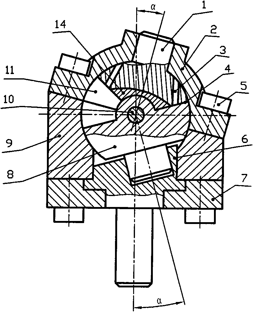
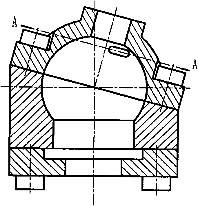
[0031] figure 1 It is a structural sectional view of an embodiment of a spherical compressor of the present invention, the spherical compressor includes a cylinder 9, a cylinder head 2, a piston 1, an insert 14, a turntable 8, a main shaft 6, a main shaft support 7 and a central pin 10, and the cylinder 9 It is connected with the cylinder head 2 through the connecting screw 5 to form a spherical inner cavity; as Figure 9 , Figure 10 As shown, the piston 1 has a spherical top surface, a piston shaft extending from the center of the spherical top surface, two side surfaces at a certain angle, an air passage 3 and a piston pin seat formed at the lower part of the two sides of the piston 1, the piston pin seat is half Cylindrical structure, with a groove in the middle of the semi-cylindrical, and a through pin hole in the axial direction; the cylinder head 2 is provided with a shaft hole matching the piston shaft, and the piston 1 can rotate freely in the shaft hole around the ...


PUM


Abstract

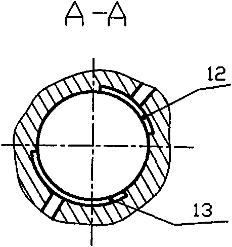
The invention designs an automatical compensation mechanism with a novel hinge sealing structure used for a spherical compressor based on the Chinese patent ZL03114505.1, wherein a cylindrical surface hinge is formed among a centrepin, a turntable pin boss and a wrist pin boss of the spherical compressor; an embedded lump is arranged in a groove on the pin boss for forming the cylindrical surface hinge; the embedded lump is in a sector block structure in which the two sides are thick and the middle part is thin; the embedded lump is arranged at the bottom of the groove; the embedded lump has a shape adaptive to that of the groove and that of an external cylindrical surface of a semicylinder lug on the pin boss for forming the cylindrical surface hinge and respectively forms seal movable fit with the groove and the semicylinder lug; and when one of the working chambers which are used for alternative compression and are formed at the two sides of the cylindrical surface hinge is in a high pressure state, the embedded lump is pressed at the side surface of the working chamber so as to enable the embedded lump to have slightly relative movement toward the low pressure side, thus the clearances close to the high pressure side between the embedded lump and the groove bottom surface as well as the cylindrical surface of the semicylinder lug are reduced, and the larger the pressure is, and the smaller the clearances are.

Description

technical field [0001] The invention relates to a hinge sealing structure, in particular to the sealing of the hinge structure used for connecting the piston of a spherical compressor and the rotating disk. Background technique [0002] The Chinese patent with the patent number ZL03114505.1 and the patent title "A Variable-capacity Mechanism for Compressors" discloses a new type of volumetric compressor, which has no intake and exhaust valves, fewer moving parts, Small vibration, high mechanical efficiency, reliable sealing and so on. [0003] But in this patent, there is implementation defect in the design of piston and rotating disk connecting hinge structure. In Chinese patent ZL03114505.1, there is a structure in which the piston pin seat matches the turntable pin seat, and is connected together by a center pin to form a cylindrical hinge connection. In this structure, a half-cylindrical groove is formed in the middle of the two pin seats. This structure is not suitabl...

Claims


Application Information

Patent Timeline
Patent Type & Authority Applications(China)
IPC IPC(8): F04C29/00
CPCF01C19/005F04C18/54F04C21/005F04C2240/20F04C2240/56F04C27/001
Inventor 王梦莹王陆一
Owner SHENZHEN SPHERICAL POWER TECH CO LTD
Learn More