
Block-based flash memory and its operation method

A storage device and block technology, applied in the field of flash memory, can solve the problems of increasing device cost and complexity

Active Publication Date: 2010-12-22
MACRONIX INT CO LTD
View PDF9 Cites 26 Cited by
  • Summary
  • Abstract
  • Description
  • Claims
  • Application Information

AI Technical Summary

Problems solved by technology

However, it also increases the cost and complexity of the device

Method used


Image

  • Block-based flash memory and its operation method
  • Block-based flash memory and its operation method
  • Block-based flash memory and its operation method

Examples


Embodiment Construction

[0062] Embodiments of the present invention are matched with the following Figure 1 to Figure 12 Describe in detail.

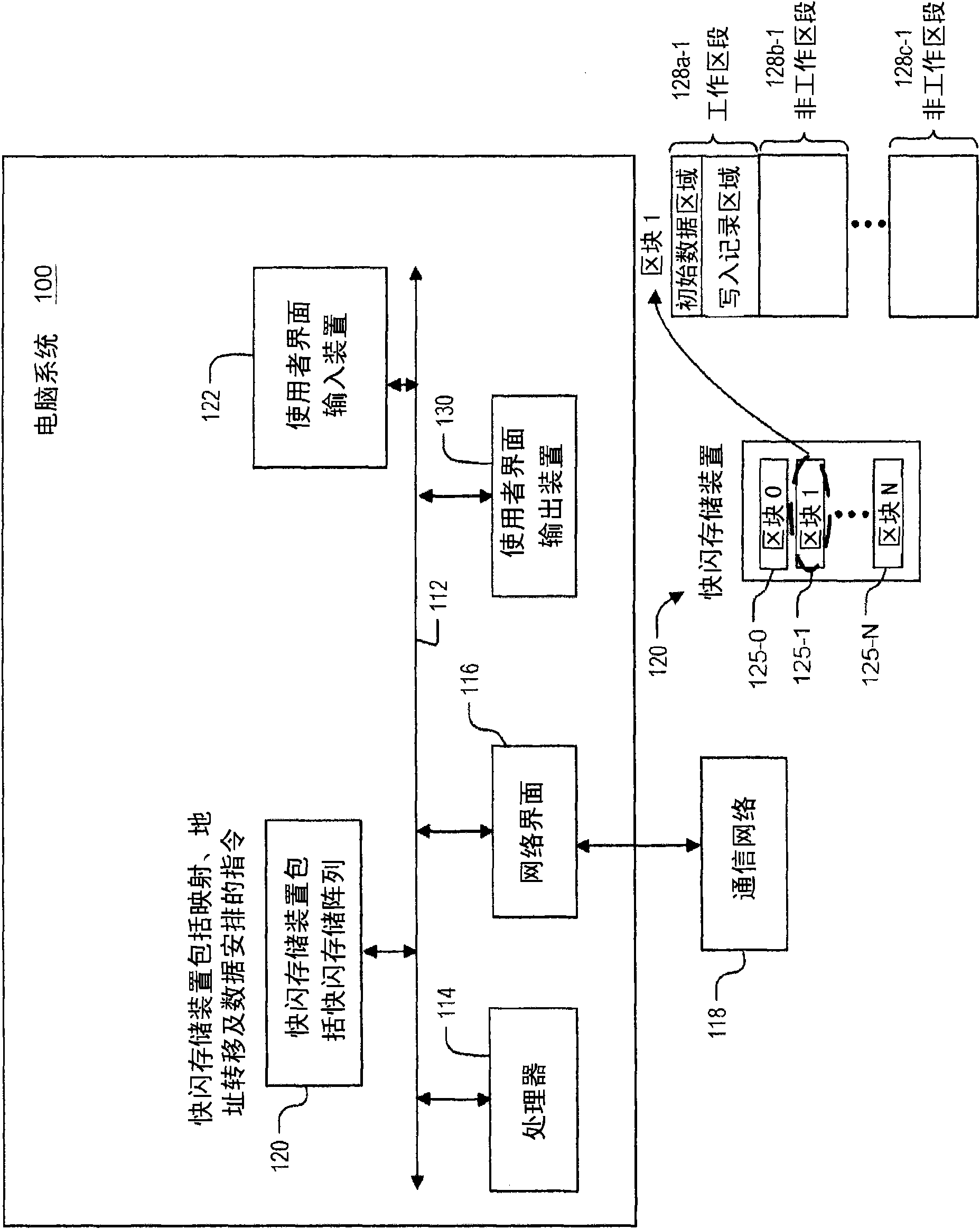
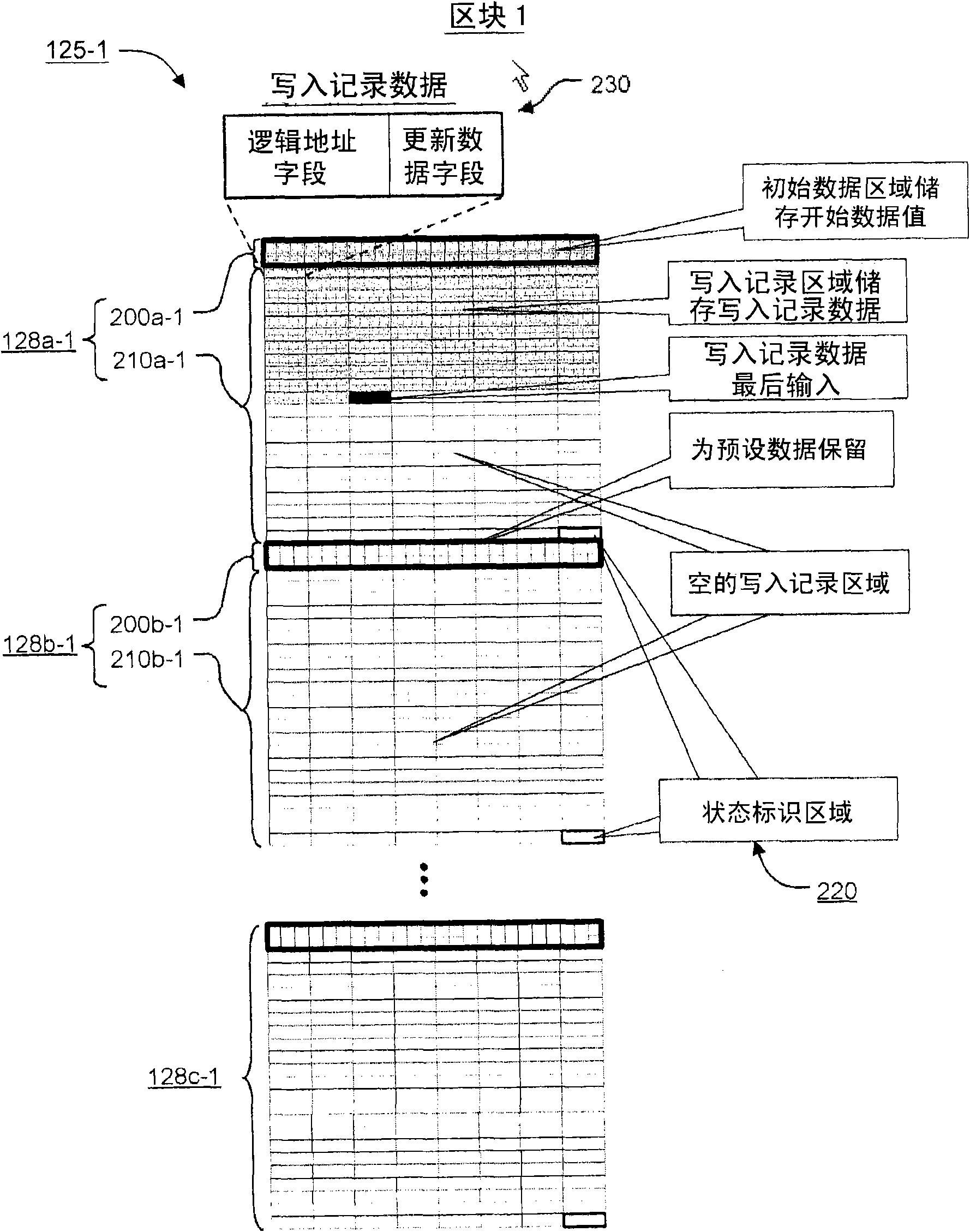
[0063] figure 1 Shown is a simplified block diagram of a computer system 100 suitable for data organization in a block-based flash memory device 120 using the techniques described herein. Computer system 100 typically includes at least one processor 114 that communicates with a number of peripheral devices via bus subsystem 112 . These peripheral devices may include a flash memory device 120 , a user interface input device 122 , a user interface output device 130 and a network interface subsystem 116 . These input and output devices may allow a user to interact with the computer system 100 . The network interface subsystem 116 serves as an interface to the external network, including an interface with the communication network 118 , and is coupled with corresponding interface devices in other computer systems through the communication network 118 . Commun...


PUM


Abstract

The invention discloses a block-based flash memory and its operation method. Techniques are described herein for managing data in a block-based flash memory device which avoid the need to perform sector erase operations each time data stored in the flash memory device is updated. As a result, a large number of write operations can be performed before a sector erase operation is needed. In addition, the block-based flash memory can emulate both programming and erasing on a byte-by-byte basis, like that provided by an EEPROM.

Description

technical field [0001] The present invention relates to flash memory technology, in particular to block-based flash memory devices and methods of operation thereof. Background technique [0002] Electrically Erasable Programmable Read Only Memory (EEPROM) and flash memory include memory cells that store electrical charge between a channel and the gate of a field effect transistor. The stored charge will affect the threshold voltage of the transistor, and the threshold voltage will be changed according to the stored charge so as to sense the indicating data. One of the most commonly used charge storage memory cells is known as a floating gate memory cell. In a floating gate memory cell, charge is stored in a layer of conductive material between the channel and the gate. Another type of charge storage memory cell is called a charge trapping memory cell, which uses a dielectric layer instead of a floating gate. [0003] The term "programming" as used herein refers to the ope...

Claims


Application Information

Patent Timeline
Patent Type & Authority Applications(China)
IPC IPC(8): G06F12/06
CPCG06F2212/7207G06F2212/7201G06F2212/7202G06F12/0246
Inventor 李祥邦董崇杰王成渊
Owner MACRONIX INT CO LTD
Learn More