
Target missile assembly detection system and method

A technology for assembly detection and target missiles, which is applied in the direction of weapon testing, weapon accessories, offensive equipment, etc., to achieve the effects of good wave absorption, low power requirements, and low cost

Inactive Publication Date: 2010-12-15
BEIJING INSTITUTE OF TECHNOLOGYGY
View PDF4 Cites 1 Cited by
  • Summary
  • Abstract
  • Description
  • Claims
  • Application Information

AI Technical Summary

Problems solved by technology

[0005] The purpose of the present invention is to solve the problem of automatic detection of whether the forward direction of the Lumber ball is aligned with the target bomb after the target bomb is assembled, and to propose a new target bomb assembly detection system and method

Method used


Image

  • Target missile assembly detection system and method
  • Target missile assembly detection system and method
  • Target missile assembly detection system and method

Examples


Embodiment Construction

[0028] The specific embodiments of the present invention will be described in further detail below in conjunction with the accompanying drawings.

[0029] A target bomb assembly detection system, such as figure 2 Shown, including oscilloscope, PIN modulator, voltage controlled oscillator, power amplifier, circulator, detector head, microwave anechoic chamber and antenna.

[0030] Wherein, the oscilloscope requires a built-in square wave signal generator;

[0031] The power amplifier requires its gain to be greater than or equal to 20 dBm;

[0032] The circulator requires that the isolation between its 2-port and 3-port is greater than or equal to 22dB;

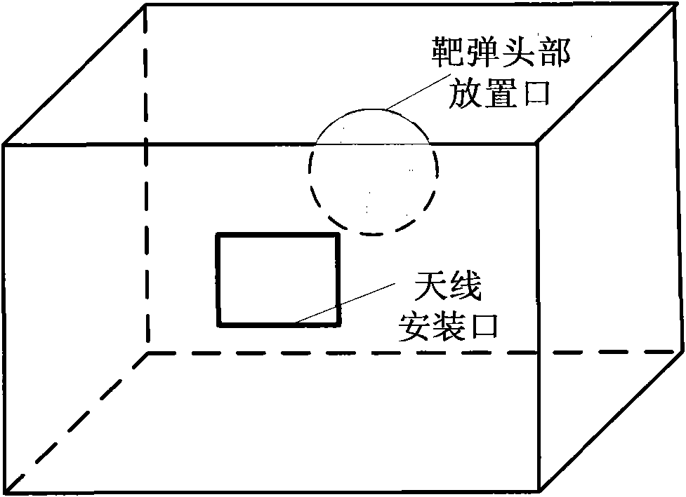
[0033] The structure of the microwave anechoic chamber is a cube, and its structure is as image 3 As shown, an antenna mounting port is opened on one surface of the darkroom; a target projectile head placement port is opened on the other side of the antenna mounting port symmetrical, the diameter of which should be the same as the max...


PUM


Abstract

The invention relates to a target missile assembly detection system and a method. The system comprises an oscillograph, a PIN modulator, a voltage controlled oscillator, a power amplifier, a circulator, a detecting head, a microwave unreflected chamber and an antenna, wherein the antenna extends into the microwave unreflected chamber from the antenna mounting port of the microwave unreflected chamber. The method comprises the following steps: after the amplitude-modulated waves, which are emitted by the antenna, are reflected by a luneberg lens in a target missile and are received by the antenna, inputting the waves to the detecting head by the circulator to detect the amplitude; inputting the detection result to the oscillograph to be displayed, thereby obtaining the oscillograph output level which reflects the position of the luneberg lens of the detected target missile; checking whether the oscillograph output level is within the range of 160-195 mV; if so, judging that the luneberg lens is placed in a proper position; and if the level is equal to the critical values of the range or beyond the range, judging that the luneberg lens is not placed in the proper position. The invention can be used for effectively detecting whether the luneberg lens is placed in the proper position on the target missile. The system has the advantages of compact structure, light weight, low cost and stable detection performance.

Description

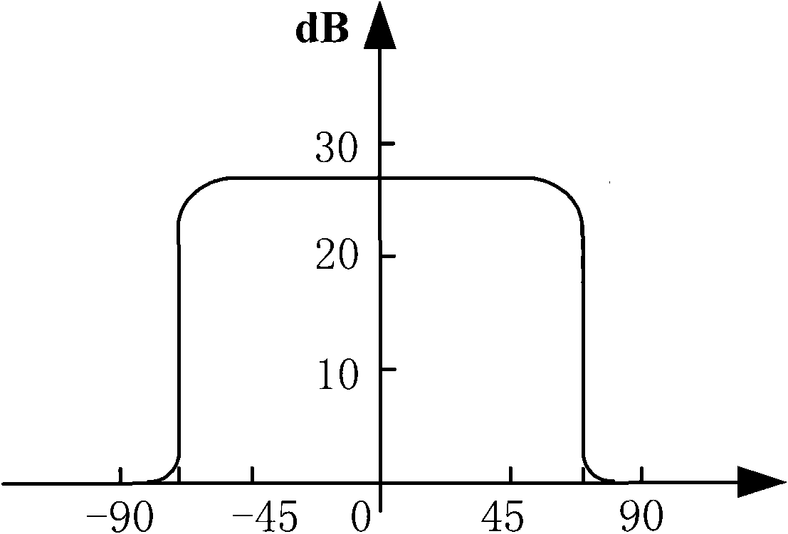
Technical field [0001] The invention belongs to the technical field of radar signal detection, and relates to a target bomb assembly detection system and a detection method. Background technique [0002] As a radar wave reflector, Lumber Ball has an effective reflection area of ​​30 times that of a triangular corner reflector under the same size. Therefore, it is often mounted on the target warhead to simulate large targets for air defense systems. [0003] Lumber Ball is made by adding a metal reflective surface to the partial surface of the Lumber lens, so the reflective characteristics are different on both sides of the metal reflective surface. Take the 140° Lumber ball reflector as an example, such as figure 1 As shown, on the side of the metal reflecting surface facing the center of the sphere, within an angle range of 140°, when the center of the antenna beam is aligned with the Dragon Ball, the radar cross-sectional area is approximately Define this range as the forward di...

Claims


Application Information

Patent Timeline
IPC IPC(8): F41A31/00
Inventor 王学田房丽丽曹欢欢雷鸥
Owner BEIJING INSTITUTE OF TECHNOLOGYGY
Learn More