
Connecting joint between hollow steel tube concrete column and steel girder and construction method thereof

A technology for steel pipe concrete columns and connection nodes, which is applied in the processing of building materials, construction, building construction, etc., can solve the problems of inability to form lateral shrinkage and shear slip, unreasonable load path transfer of nodes, and beam web technology Large hole stress concentration and other problems, to achieve the effect of facilitating mechanized production, improving constructability, and improving seismic performance

Inactive Publication Date: 2010-12-15
SOUTH CHINA UNIV OF TECH
View PDF6 Cites 40 Cited by
  • Summary
  • Abstract
  • Description
  • Claims
  • Application Information

AI Technical Summary

Problems solved by technology

The research on the earthquake damage of the Northridge earthquake in the United States in 1994 and the Kobe earthquake in Japan in 1995 showed that the joints using all-welded or bolted-welded joints suffered severe tearing and brittle damage, and also exposed this kind of joint connections that rely too much on welds. defects, such as: on-site welding construction is difficult and the quality of the weld is difficult to guarantee; welding has a great influence on the heat of the steel pipe wall, which is likely to cause brittle damage and affect the ductility of the joint; the steel at the connection part has three-dimensional stress, which cannot form lateral shrinkage and Shear slip, resulting in the formation of a high stress concentration area at the weld of the groove of the beam flange; there is a large stress concentration at the root of the process hole of the beam web, and the transfer of the load path of the node is unreasonable, etc.

Method used


Image

  • Connecting joint between hollow steel tube concrete column and steel girder and construction method thereof
  • Connecting joint between hollow steel tube concrete column and steel girder and construction method thereof
  • Connecting joint between hollow steel tube concrete column and steel girder and construction method thereof

Examples


Embodiment Construction

[0031] The specific implementation of the present invention will be described in further detail below in conjunction with the accompanying drawings, but the implementation and protection scope of the present invention are not limited thereto.

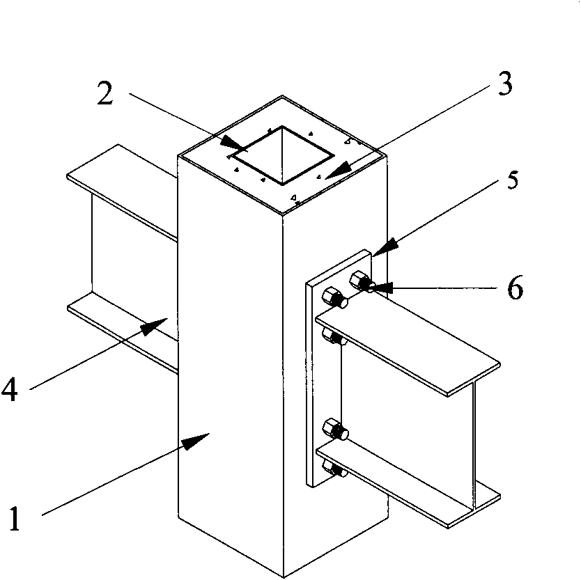
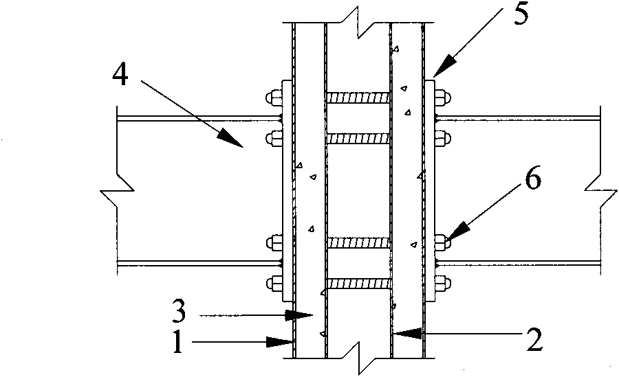
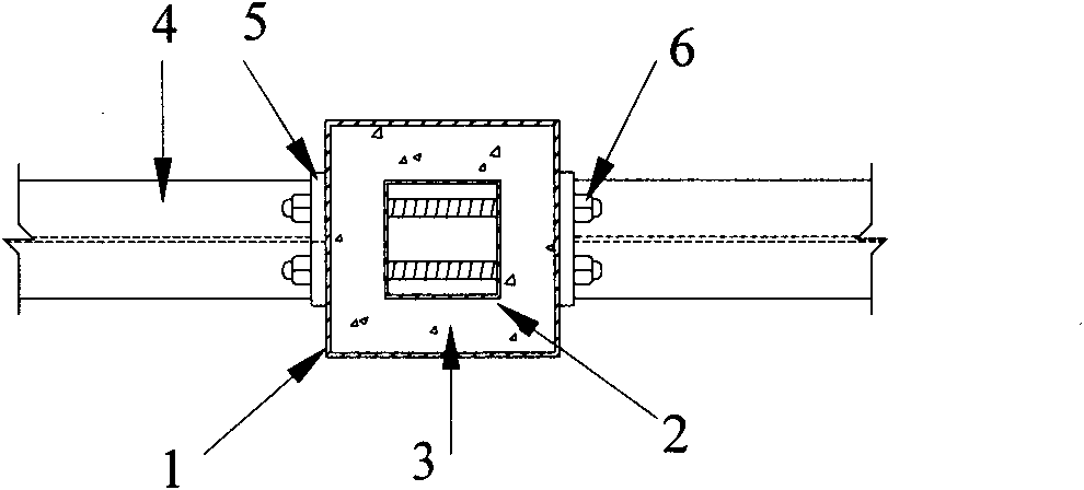
[0032] Such as Figure 1 ~ Figure 3 As shown, the connection node between the hollow concrete-filled steel pipe column and the steel beam includes a hollow concrete-filled steel pipe column, a steel beam 4, an end plate 5 and a high-strength bolt 6 connecting the hollow concrete-filled steel pipe column and the steel beam at the joint, and the end plate 5 Welded at the end of the steel beam 4, bolt holes 7 for the high-strength bolts 6 to pass through are opened on the end plates at the joints and the outer steel pipes of the hollow concrete-filled steel tube columns; the high-strength bolts 6 pass through the end plates 5 The node connection is realized with the bolt hole 7 on the hollow concrete-filled steel tube column. According to...


PUM


Abstract

The invention discloses a connecting joint between a hollow steel tube concrete column and a steel girder and a construction method thereof. The joint comprises a hollow steel tube concrete column, a steel girder, an end plate and a high-strength bolt, wherein the end plate is welded at the steel girder end; the steel girder end at the joint is connected with the hollow steel tube concrete column through the end plate and a bolt and is connected with a column through the prestressed high-strength bolt. In the construction method, the concrete in the steel tube can be prefabricated or cast in situ; the end plate can be welded in a factory; bolt holes on the end plate and the steel tube are preformed in the factory; and only bolt connection needs on-site construction. The joint structure has the advantages of economy, practicality, definite force transmission, simple manufacture, high prefabrication degree, convenient construction, and capacities of avoiding on-site welding and improving joint shock resistance and construction benefit.

Description

technical field [0001] The invention relates to a building structure node, in particular to a connection node between a hollow steel pipe concrete column and a steel beam and a construction method thereof. Background technique [0002] The hollow concrete-filled steel tube column is a new type of concrete-filled steel tube structure formed by filling concrete between the inner and outer layers of steel tubes. Compared with the traditional solid steel tube concrete structure, it can reduce the structural weight and increase the bending stiffness of the structure, and has a good application prospect. . The hollow section of the inner steel pipe can also be used as a building threading pipe or a building drainage pipe. Its cross-sectional forms are various, such as square-in-square, square-in-circle, square-in-rectangle, rectangle-in-rectangle, etc. At present, the research on hollow concrete filled steel tubes is mainly limited to the column members, and the research on join...

Claims


Application Information

Patent Timeline
IPC IPC(8): E04B1/58E04G21/14
Inventor 何文辉王湛
Owner SOUTH CHINA UNIV OF TECH
Learn More