Driving device for fan-shaped pouring ladle

A technology of driving device and pouring ladle, applied in the field of driving device, can solve the problems of easy wear of constant velocity plate and support arm roller, uneven wall thickness of ductile iron pipe, inability of molten iron to be constant velocity, etc., so as to avoid economic loss and ensure pouring Quality, the effect of reducing the failure rate

Inactive Publication Date: 2010-12-15
XINXING DUCTILE IRON PIPES CO LTD
View PDF1 Cites 7 Cited by
  • Summary
  • Abstract
  • Description
  • Claims
  • Application Information

AI Technical Summary

Problems solved by technology

[0002] The pouring system of the water-cooled metal ductile iron pipe centrifuge is a key component in the production process of the water-cooled metal ductile iron pipe. In order to ensure the pouring quality in the actual production process, the pouring system must pour molten iron into the centrifuge at a constant speed during the pouring process. Otherwise, the wall thickness of the ductile iron pipe produced will be uneven, resulting in substandard products, which will bring economic losses to the production enterprise. Whether the pouring system can be poured at a uniform speed depends on the structure of the pouring ladle and the performance of the pouring ladle driving device. Action, the existing pouring ladle drive system includes oil cylinder, pull arm, support arm, support arm roller, constant velocity plate and bracket for supporting the ladle. In order to achieve constant velocity and constant velocity pouring, fan pouring is used in the pouring system The fan-shaped casting bag is installed on the pouring frame by means of a rotating shaft, and the brackets are fixed on both sides of the fan-shaped casting bag. On both sides, the constant velocity plate is in contact with the supporting arm roller fixedly installed on the supporting arm. The two sides of the supporting bracket are respectively hinged with hydraulic cylinders, and the other end of the hydraulic cylinder is hinged at the bottom of the pouring frame. , the hydraulic cylinder moves at a constant speed, and the outer arc of the constant velocity plate cooperates with the supporting arm roller to realize the constant angular velocity rotation of the fan-shaped casting ladle and achieve uniform casting. Although it is rolling friction, after a period of use, the constant velocity plate and the supporting arm roller are easy to wear or get stuck, causing molten iron to not flow out of the fan-shaped ladle at a constant velocity, directly affecting the quality of the casting, and bringing economic losses to the production enterprise.

Method used


Image

  • Driving device for fan-shaped pouring ladle
  • Driving device for fan-shaped pouring ladle

Examples


Embodiment Construction

[0010] In order to make the above objects, features and beneficial effects of the present invention more obvious and easy to understand, the technical solutions in the embodiments of the present invention will be clearly and completely described below with reference to the drawings and specific implementation manners in the embodiments of the present invention.

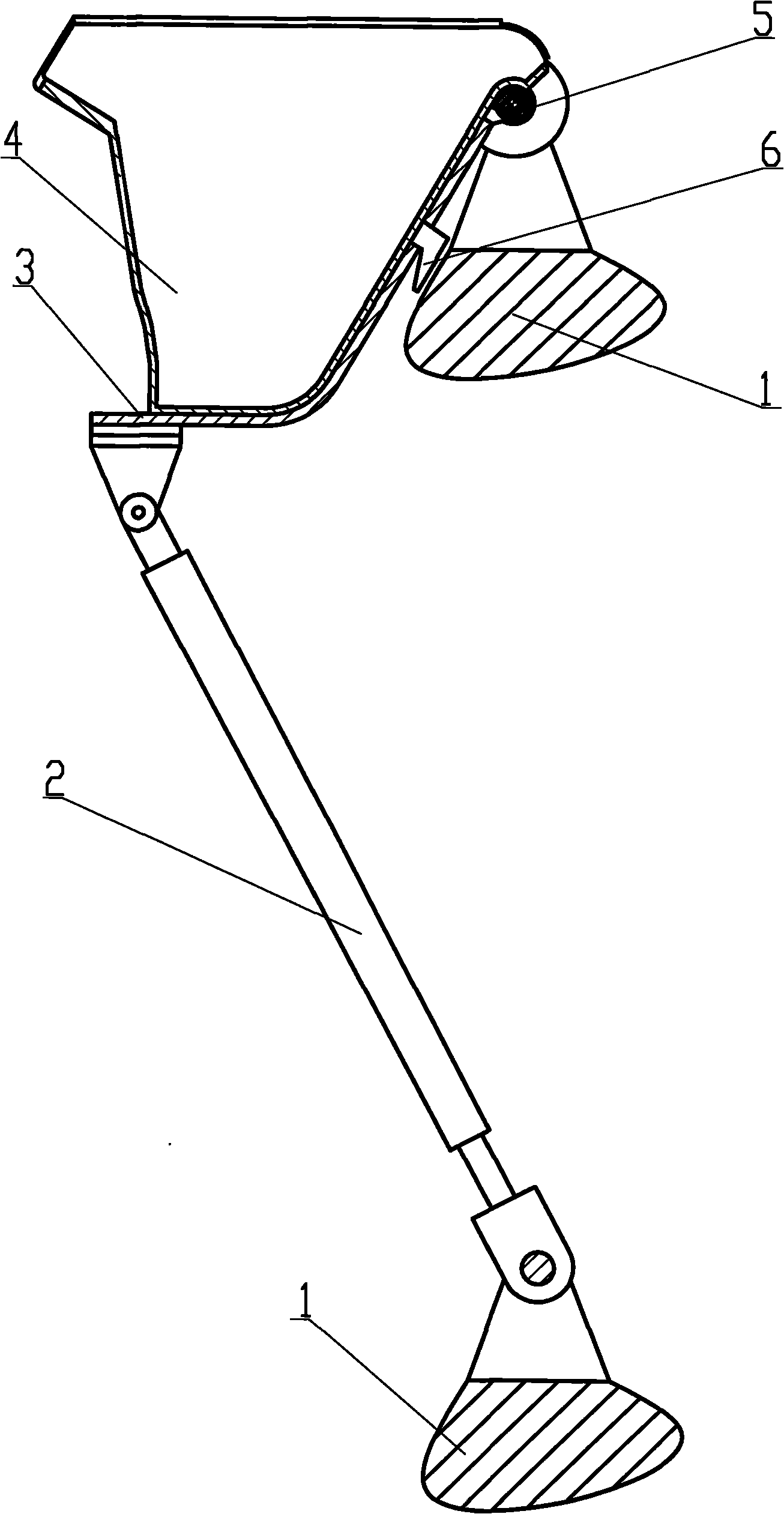
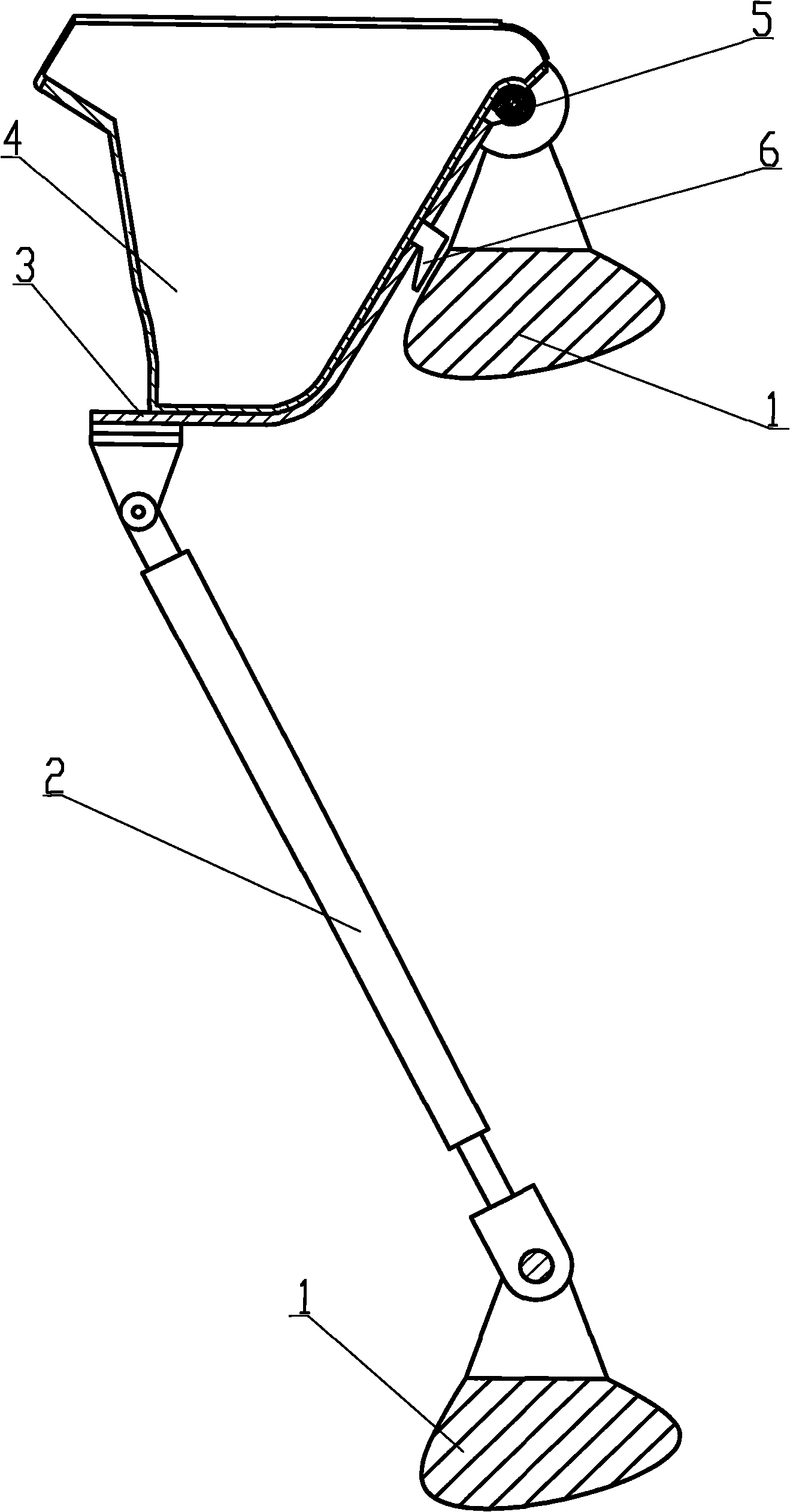
[0011] like figure 1 The key improvement of the fan-shaped ladle driving device shown is that it includes a bracket 3 fixedly installed at the bottom of the fan-shaped ladle 4 and hydraulic cylinders 2 symmetrically arranged on both sides of the fan-shaped ladle; The rotating shaft 5 is fixedly installed on the top of the casting frame 1, and an angular displacement sensor and an angular velocity sensor are arranged on the rotating shaft 5, and the signal output ends of the angular displacement sensor and the angular velocity sensor are connected with the hydraulic station control circuit of the driving hydraulic cylin...


PUM


Abstract

The invention discloses a driving device for a fan-shaped pouring ladle. The key improvement is that the driving device comprises a bracket and a hydraulic cylinder, wherein the bracket is fixedly arranged at the bottom of the fan-shaped pouring ladle; the hydraulic cylinder is symmetrically arranged on two sides of the fan-shaped pouring ladle; one end of the hydraulic cylinder is hinged at the bottom of the bracket; the bracket is attached with the rear external wall and bottom of the fan-shaped pouring ladle; a positioning hook arranged on the rear wall of the fan-shaped pouring ladle is matched with a positioning hole on the bracket; and the other end of the hydraulic cylinder is hinged at the bottom of a pouring framework. The driving device has the advantages that: an angular displacement sensor and an angular speed sensor are arranged on the rotating shaft of the fan-shaped pouring ladle; two sensors transmit acquired signals to a control circuit of a hydraulic station; the control circuit regulates the moving speed of the hydraulic cylinder according to the signals, so that the constant-speed flowing of liquid iron is ensured by the fan-shaped pouring ladle at different angles, the quality of castings is ensured and the economic loss of production enterprises caused by unqualified castings is avoided.

Description

technical field [0001] The invention relates to a driving device, in particular to a fan-shaped pouring ladle driving device applied to the pouring system of a water-cooled metal ductile iron tube centrifuge. Background technique [0002] The pouring system of the water-cooled metal ductile iron pipe centrifuge is a key component in the production process of the water-cooled metal ductile iron pipe. In the actual production process, in order to ensure the pouring quality, the pouring system is required to pour the molten iron into the centrifuge at a constant speed during the pouring process. Otherwise, the wall thickness of the ductile iron pipe produced will be uneven, resulting in unqualified products, which will bring economic losses to the production enterprise. Whether the pouring system can pour at a constant speed depends on the structure of the pouring ladle and the driving device of the pouring ladle. The existing casting ladle drive system includes oil cylinder, p...

Claims


Application Information

Patent Timeline
Patent Type & Authority Applications(China)
IPC IPC(8): B22D13/10B22D13/02
Inventor 闫现臣刘文波尹竹廷张国生张云波李军
Owner XINXING DUCTILE IRON PIPES CO LTD
Why Eureka
Try Eureka