Illuminating device, display device and television receiver

A lighting device and a mounting part technology, which can be applied to lighting devices, components of lighting devices, lighting and heating equipment, etc., can solve problems such as being unable to stably support optical sheets.

Inactive Publication Date: 2010-12-08
SHARP KK
View PDF1 Cites 6 Cited by
  • Summary
  • Abstract
  • Description
  • Claims
  • Application Information

AI Technical Summary

Problems solved by technology

However, when the width is extremely narrow, there is a possibility that the optical sheet such as a diffuser cannot be stably supported.

Method used


Image

  • Illuminating device, display device and television receiver
  • Illuminating device, display device and television receiver
  • Illuminating device, display device and television receiver

Examples


Embodiment Construction

[0048] Embodiments of the present invention will be described with reference to the drawings.

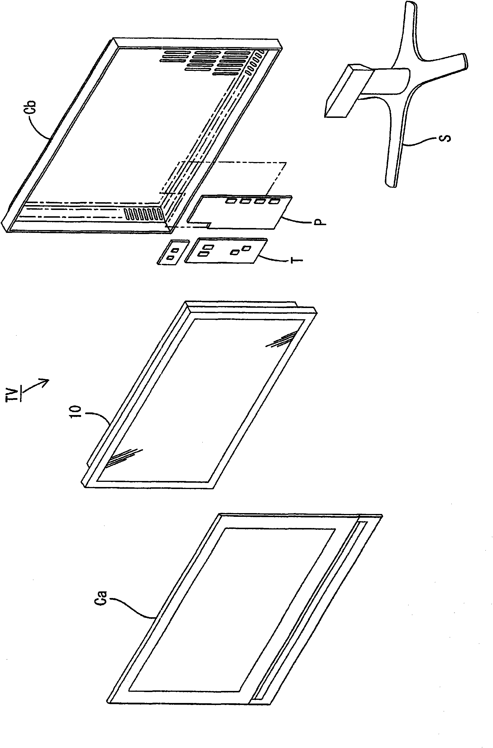
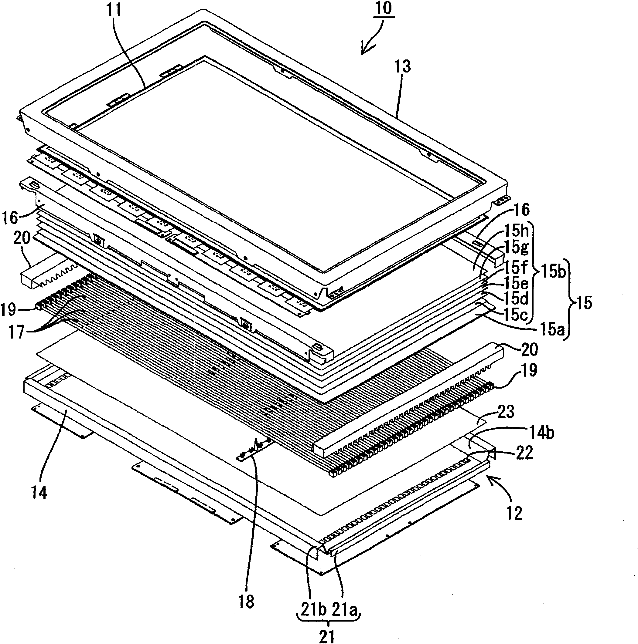
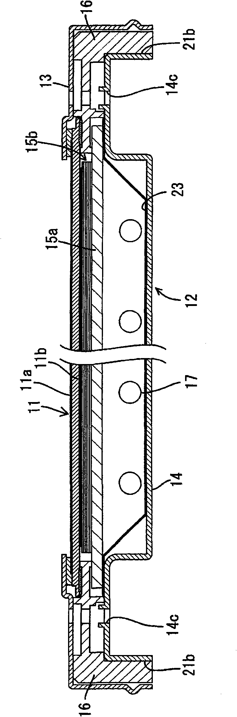
[0049] figure 1 is an exploded perspective view of a schematic configuration of a television receiving device according to this embodiment, figure 2 yes means figure 1 An exploded perspective view of the schematic structure of the liquid crystal display device included in the television receiving device of image 3 is to mean along figure 2 An enlarged cross-sectional view of the main part of the cross-sectional structure in the short-side direction of the liquid crystal display device, Figure 4 is to mean along figure 2 An enlarged sectional view of main parts of the sectional structure in the longitudinal direction of the liquid crystal display device. in addition, Figure 5 yes means figure 2 A perspective view of the surface side structure of the lamp holder of the backlight device of the liquid crystal display device, Figure 6 is a perspective view showing the str...


PUM


Abstract

An illuminating device (12) comprises a light source (17) including conductive sections (19) on its ends, an optical sheet (15) disposed on a light emitting side of the light source (17), and light-shield cover members (20) covering the ends of the light source (17), wherein each of the cover members (20) has a cover section (20z) for covering the light source (17) and an optical sheet mounting section (20a) disposed on the light emitting side of the cover section (20z) for mounting the optical sheet (15), and the optical sheet mounting section (20a) comprises a protruding section (71) protruding toward the center of the light source (17).

Description

technical field [0001] The invention relates to an illuminating device, a display device and a television receiving device. Background technique [0002] Since a liquid crystal panel used in a liquid crystal display device such as a liquid crystal television does not emit light by itself, it is necessary to separately install a backlight device as an illuminating device. Such a backlight device is known to have a structure including a plurality of backlights arranged in parallel, a lamp holder covering the ends of the backlights, and a diffuser plate arranged on the lamp holder, as disclosed in Patent Document 1, for example. The lamp holder disclosed in this patent document 1 has a function of fixing the backlight to the rear chassis, and also has a function of supporting optical sheets such as a diffuser plate. [0003] Patent Document 1: Japanese Patent Laid-Open No. 2006-235127 [0004] In recent years, there has been an increasing demand for thinner and narrower frame...

Claims


Application Information

Patent Timeline
IPC IPC(8): F21S2/00F21V17/00G02F1/13357H04N5/66F21Y103/00
CPCG02F1/133604G02F1/133611G02F1/133608
Inventor 黑水泰守横田匡史山本修己山本香织
Owner SHARP KK
Why Eureka
Try Eureka