


Quick Research
Generate reliable direction feasibility study reports for your R&D in just a few steps.

Technical Q&A
Discover and master advanced knowledge NOW. Basics, ideas, possibilities, all at once.

Find Solutions
As an expert in R&D theories, this can generate solutions to your technical problems instantly.

Evaluate Feasibility
Analyze your overall solution with one click, know your potential R&D risks in advance.

Monitor Landscape
Get weekly tech updates, stay abreast of the latest tech innovations and key insights.
Device for pumping gaseous suspensions, particularly fiber suspensions
A technology of fiber materials and suspended matter, which is applied to parts of pumping devices for elastic fluids, pumps for special fluids, liquid fuel engines, etc., can solve the problems of not setting fluidized rotors, etc., and save additional equipment Effect
- Summary
- Abstract
- Description
- Claims
- Application Information
AI Technical Summary
Problems solved by technology
Method used
Image


Examples
Embodiment Construction
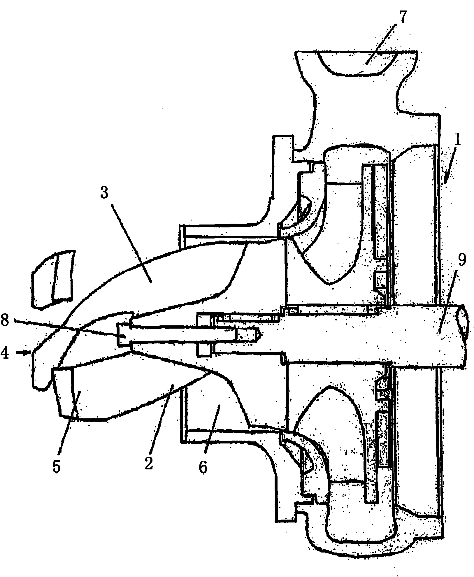
[0017] figure 1 A pump 1 with a fluidizing rotor 2 with a hub 3 is shown. At the inlet end 4 , the surfaces of the blades 5 are arranged perpendicular to the axis of the fluidizing rotor 2 . Hydraulic inlet losses are thereby minimized, thereby increasing the efficiency of the pump. The fluidization rotor 2 is arranged in the suction connection 6 of the pump 1 , wherein the fluidized suspension, in particular a fibrous material suspension, is transported via the rotor to the pressure connection 7 . The fluidization rotor 2 protrudes here beyond the suction pipe connection 6 into, for example, a container from which the suspension is to be pumped, and this makes it possible for the suspension to be more easily introduced into the suction pipe connection 6 . The hub 3 of the fluidizing rotor 2 is fixed on the pump shaft 9 by means of screws 8 .
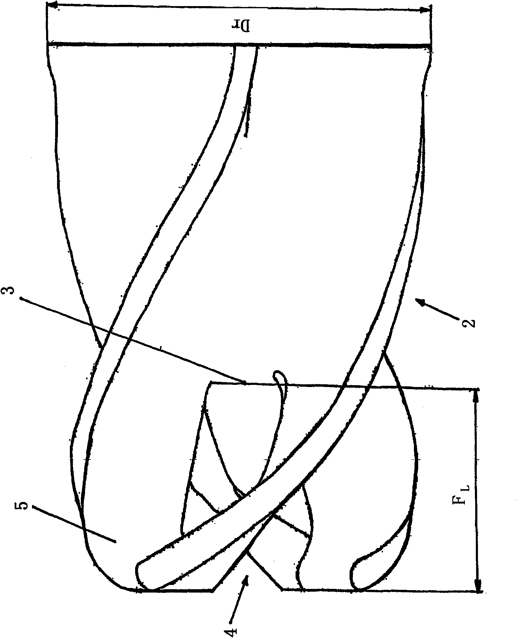
[0018] figure 2 The fluidizing rotor 2 according to the invention of the pump 1 is shown. It can be seen particularly clearly he...
PUM
 Abstract
Description
Claims
Application Information
 - R&D Engineer
- R&D Manager
- IP Professional
- Industry Leading Data Capabilities
- Powerful AI technology
- Patent DNA Extraction
Browse by: Latest US Patents, China's latest patents, Technical Efficacy Thesaurus, Application Domain, Technology Topic, Popular Technical Reports.
© 2024 PatSnap. All rights reserved.Legal|Privacy policy|Modern Slavery Act Transparency Statement|Sitemap|About US| Contact US: help@patsnap.com